 Skip to content
SMD vs Through-Hole Rectifiers: Prevent Package Errors Before PCB Release
Last Updated: 2026-09-23
Quick Answer
Comparing SMD vs through-hole rectifiers requires the exact package drawing, board interface, polarity and assembly process. A matching voltage and current rating does not make the packages interchangeable. Also, DO does not mean through-hole: DO-41 is an axial example, while DO-214AC is the surface-mount SMA designation used by many rectifiers.
A replacement fits the electrical comparison sheet, but production discovers that it cannot be placed on the existing board. The error may have begun much earlier, when a BOM description used only “1 A rectifier” or treated a package-family label as a complete mechanical specification.
Package review is most useful before a footprint is released and before purchasing accepts an alternate.
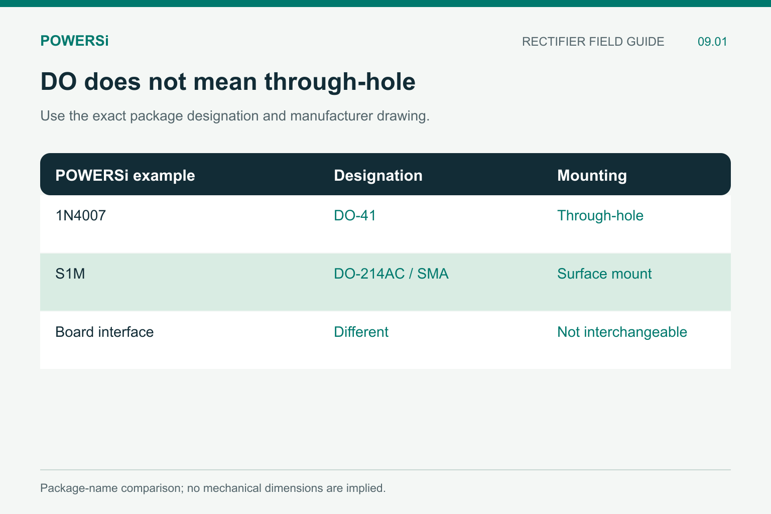
DO-41 and DO-214AC belong to different mounting arrangements.
Decode the Exact Package Designation
SMD describes surface-mount assembly. Through-hole describes leads inserted into board holes. These are mounting categories, not complete package names. Record the manufacturer’s exact designation and drawing revision as well.
The letters “DO” are not a reliable way to distinguish them. In the POWERSi documents used here, 1N4001–1N4007 use the axial DO-41 package, while S1A–S1M use DO-214AC, commonly called SMA, for surface mounting.
| Example | Package designation | Board interface |
|---|---|---|
| POWERSi 1N4007 family member | DO-41 | Axial leads and through-hole assembly |
| POWERSi S1M family member | DO-214AC / SMA | Surface-mount terminals and pads |
These examples explain the naming distinction. They are not a declaration that the two products can be exchanged on the same PCB.
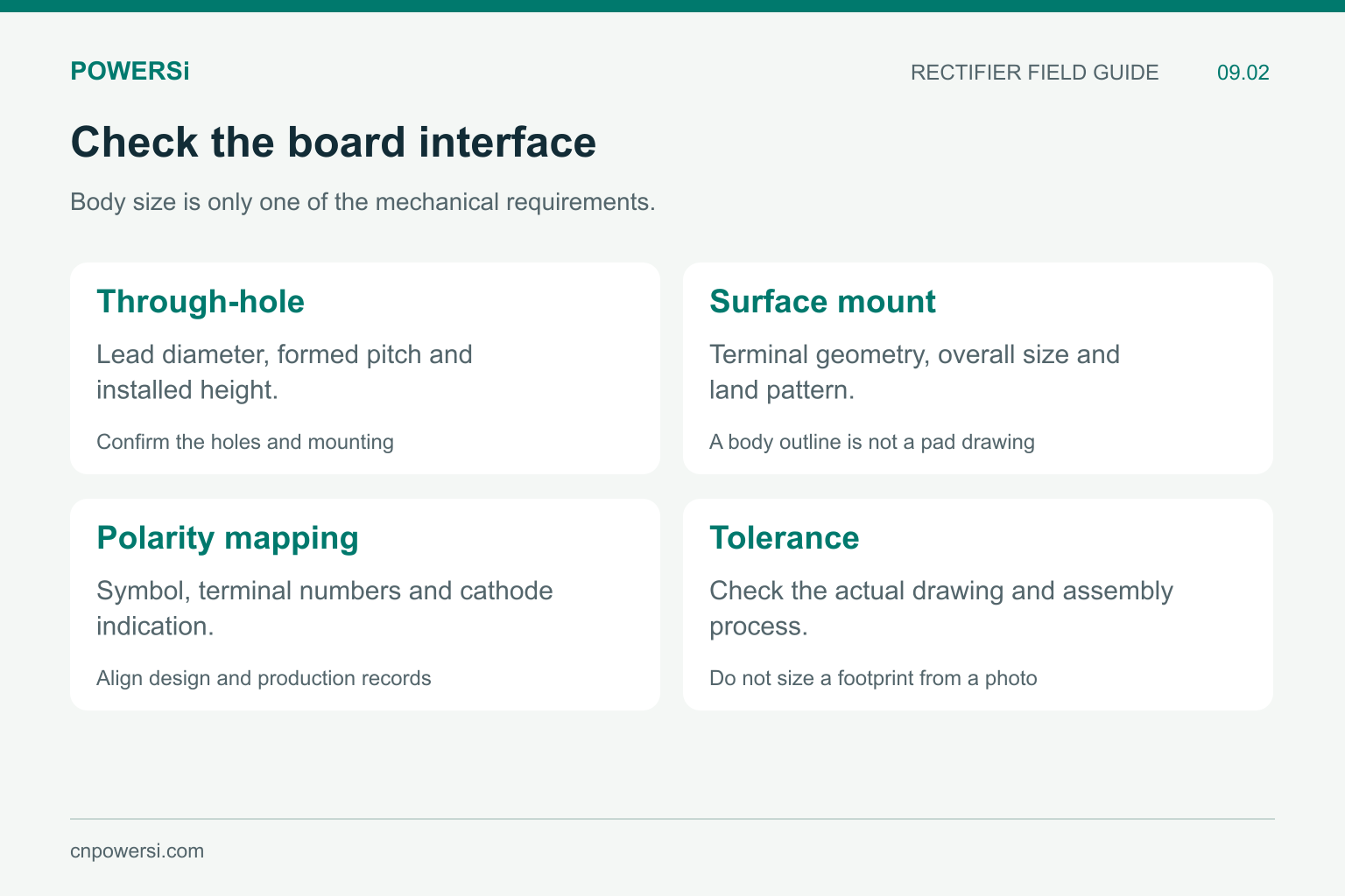
Use controlled drawings to make a footprint decision.
Compare the Board Interface, Not Just Body Length
For an axial part, review body length and diameter, lead diameter, formed lead spacing, component height and the chosen mounting arrangement. The board hole size and placement must suit the actual leads and assembly tolerances.
For a surface-mount part, review the terminal geometry, overall dimensions, height and recommended land pattern. A body outline is not automatically a recommended solder-pad drawing. Terminal access, solder mask and manufacturing tolerances belong in the footprint decision.
Do not release a footprint from a product photograph. Photos can help identify a part, but they do not establish mechanical tolerances. A package drawing and the actual production process provide the needed dimensions and constraints.
Carry Polarity Through Every Record
The POWERSi DO-41 and S1A–S1M documents identify the cathode end with a color band. The board footprint, silkscreen, placement data and inspection criteria should express the same orientation clearly.
A reversed component can result from a library or orientation error even when the purchased model is correct. Check how the terminal numbering in the design tool maps to the manufacturer’s polarity information. Do not assume that a generic library symbol and an imported footprint were created using the same convention.
For production, use the actual tape orientation or formed-lead delivery specification. The component marking and the feeder or insertion setup answer related but different questions.
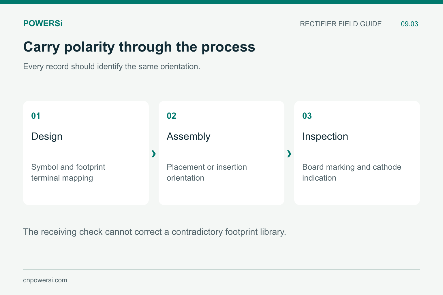
A correct part can still be assembled in the wrong orientation.
Thermal Conditions Can Change With the Package
An apparent electrical match can hide different thermal assumptions. POWERSi S1A–S1M lists a 1.0 A average rectified-current rating at a lead temperature TL = 110 °C. The POWERSi 1N4001–1N4007 document lists 1.0 A at ambient temperature TA = 75 °C with a 9.5 mm lead length. Both documents also specify waveform and loading conditions.
Those are not identical test environments. The number “1 A” therefore does not prove equal temperature in a finished board. Copper area, lead mounting, airflow and nearby heat sources affect the installed result.
Keep TA, TL, TC and TJ distinct. They refer to ambient, lead, case and junction temperatures. Substituting one for another can make an otherwise careful comparison invalid.
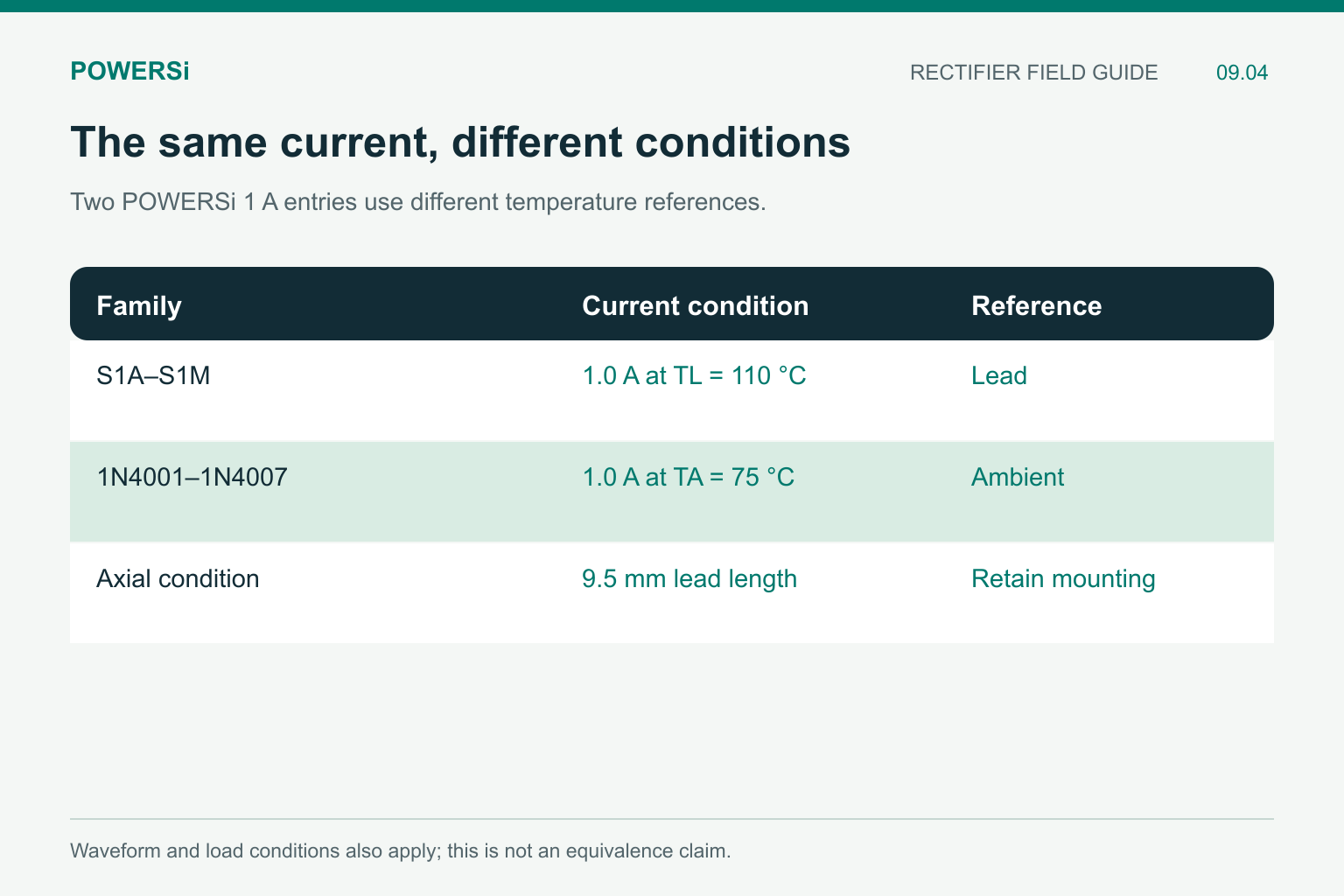
A shared 1 A number does not prove equal installed temperature.
Confirm the Assembly and Delivery Format
Surface-mount and through-hole production use different handling and soldering arrangements. Confirm the intended process, allowable profile, terminal finish, packaging format and inspection access with the manufacturing team.
A tape-and-reel quantity is an ordering attribute, not proof that the part fits the feeder or footprint. Similarly, an axial body does not establish the required lead forming or insertion pitch. Specify the delivered configuration that production needs.
Treat a package change as a controlled design change. It can affect the layout, assembly data, inspection criteria and thermal performance, even when the circuit symbol stays the same.
Use a Release Gate Before the Purchase Order
Keep a compact package record with the exact manufacturer code, outline drawing, footprint identifier, polarity mapping and approved delivery format. Attach the electrical and thermal comparison separately so a mechanical match is not mistaken for complete qualification.
For a new footprint or a changed package, check a representative sample against the board and assembly process before committing to volume. Record who approved the footprint and which board revision it applies to. Receiving should then compare the shipment against that same identity.
The release decision should be specific: approved for this footprint and assembly revision, or a board change is required. “Similar package” is too vague to guide a repeat order.
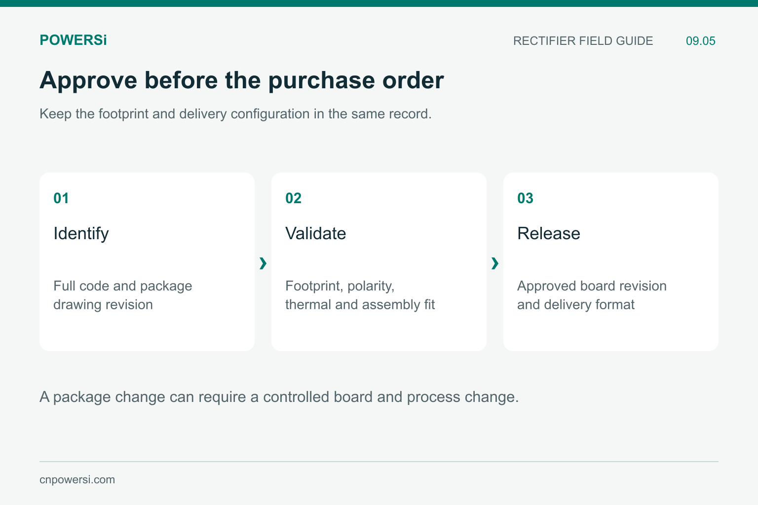
An exact approval is more useful than “similar package.”
Key Takeaways
- SMD and through-hole are mounting categories, not full package identities.
- DO-41 and DO-214AC show why “DO” cannot mean through-hole by default.
- Check dimensions, polarity, thermal assumptions and the production process separately.
- Tie the approved package to the footprint and board revision before ordering.
Conclusion
Preventing rectifier package errors starts with a precise mechanical identity. Confirm the board interface and manufacturing requirements alongside the electrical selection, and keep that approval visible from design release through receiving.
Explore POWERSi rectifier options or send the existing part, footprint requirements and assembly process to [email protected].
FAQs
Does a DO package code always mean through-hole?
No. DO-41 is an axial example, while DO-214AC identifies the surface-mount SMA package.
Can matching current ratings establish package equivalence?
No. The thermal conditions, dimensions, connections and assembly requirements also need comparison.
Can I draw the footprint from a product photo?
A photo does not establish tolerances or a solder land pattern. Use the manufacturer’s drawing and the production requirements.
Is cathode orientation only a receiving check?
No. It must be consistent across the schematic, footprint, board marking, placement data and inspection process.
What belongs in a package approval record?
Include the full code, drawing revision, footprint, polarity mapping, board revision, delivery format and assembly approval.


