 Skip to content
Line-Frequency vs High-Frequency Rectifiers: Choose by Circuit Position
Last Updated: 2026-09-23
Quick Answer
Choosing line-frequency vs high-frequency rectifiers starts with the waveform at the diode, not the product’s size or the power supply’s name. Identify the circuit position, then compare blocking voltage, current, commutation behavior and cooling. One switching power supply can contain both a line-input rectifier and diodes that switch much faster.
A buyer sees “switching power supply” on an assembly description and requests a high-frequency diode for every rectifier position. Another chooses a general-purpose part because its voltage and current numbers match the original. Both shortcuts miss the same information: what the diode actually does in that circuit.
Equipment switching frequency does not describe every diode position.
Map the Diode Positions First
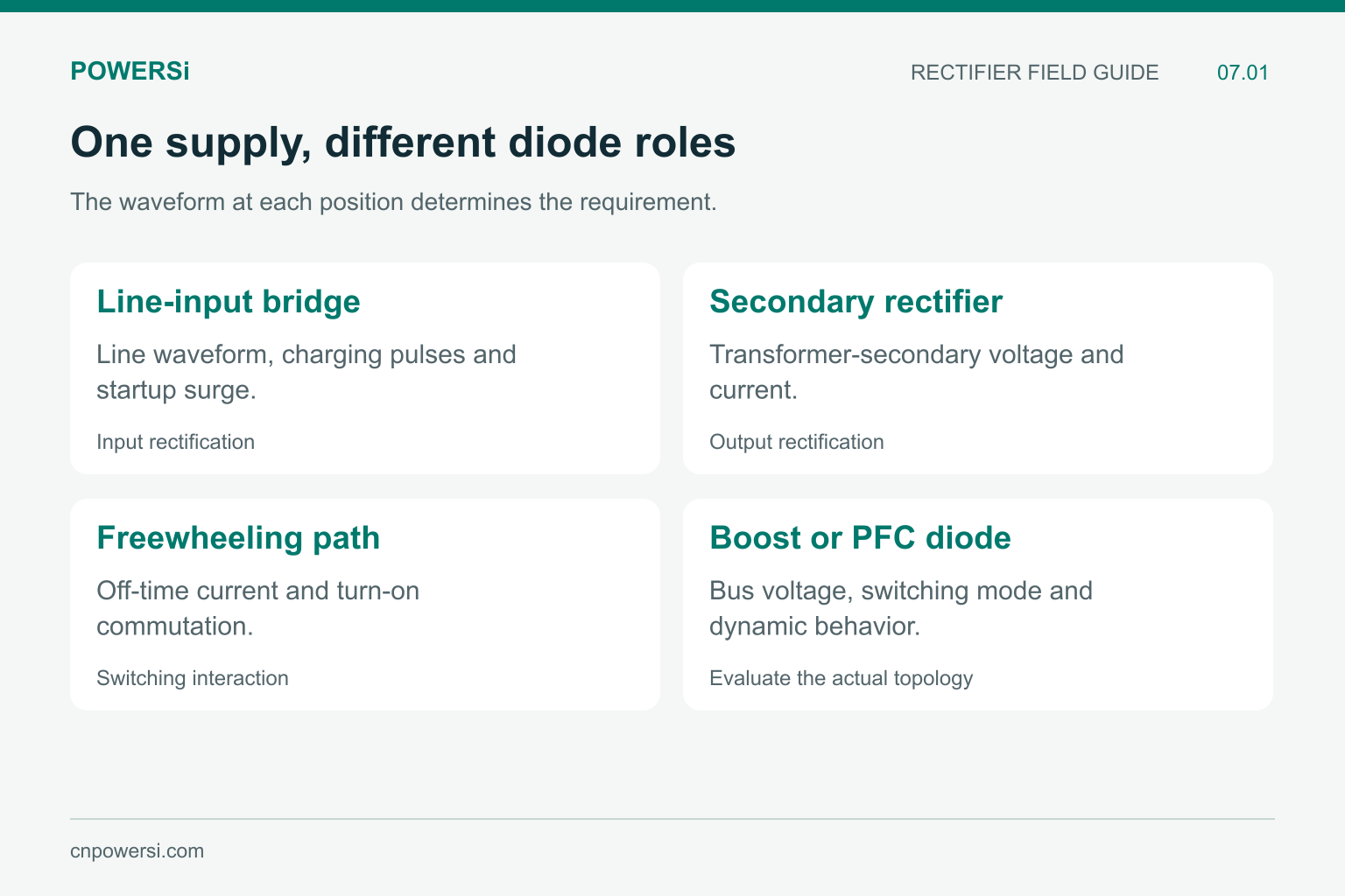
Consider a conventional power supply with an AC input bridge, a DC link and a high-frequency converter. The input bridge rectifies the incoming line waveform. Diodes in the converter or its secondary can commutate with the switching stage. A freewheeling diode may carry current while the associated switch is off and then recover when that switch turns on.
These positions need separate evaluations. The equipment-level switching frequency does not describe every diode inside the enclosure.
| Position | Conditions to investigate |
|---|---|
| AC line-input rectifier | Line waveform, capacitor-charging pulses, startup surge and heat |
| Transformer-secondary rectifier | Secondary voltage, conduction waveform and commutation |
| Freewheeling diode | Off-time current, turn-off commutation and reverse stress |
| Boost or PFC diode | Bus voltage, switching mode, current and recovery or capacitive charge |
This is a functional map, not a declaration that one technology is correct for every circuit in each category.
Line Frequency Does Not Mean Gentle Current
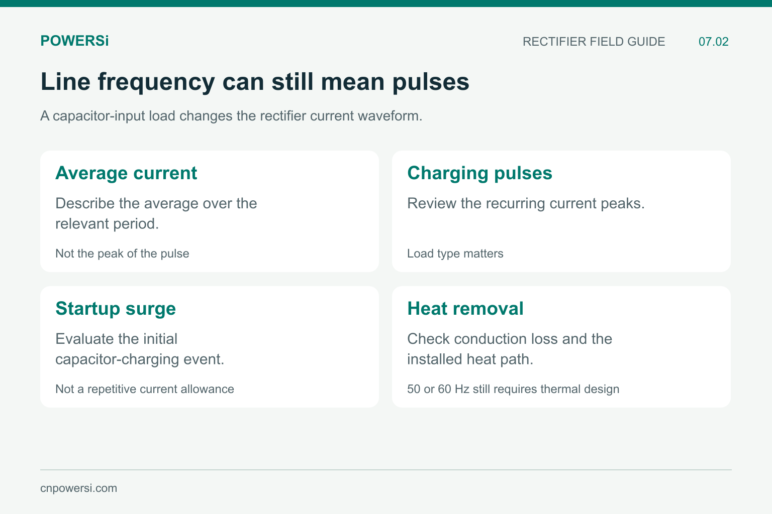
A bridge feeding a large capacitor can conduct in relatively narrow pulses near the line-voltage peaks. Its current waveform differs from a smooth resistive load. Startup can create an additional charging surge, so average current alone does not establish suitability.
Distinguish repetitive operating pulses from the non-repetitive surge rating. Cooling also remains important at 50 or 60 Hz. A device that is correctly classified as a line rectifier can still overheat because the current waveform, ambient conditions or heat path exceed the design assumptions.
For procurement, record the load type and expected current waveform. “Low frequency” is not a substitute for those details.
A low line frequency does not make the current stress negligible.
High-Frequency Positions Need Dynamic Evidence
In a PN rectifier, stored charge must be removed as the diode changes from conduction to reverse blocking. That transition can affect both the diode and the switch that forces commutation. Recovery time, recovered charge and waveform shape describe different aspects of the event.
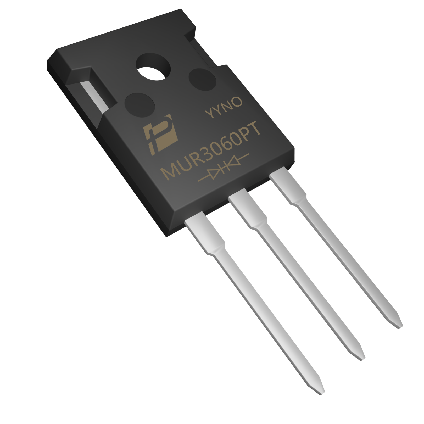
The POWERSi MUR3060PT is a recovery rectifier with a specified maximum trr of 50 ns at Tj = 25 °C, IF = 0.5 A, IR = 1.0 A and Irr = 0.25 A. This entry supplies a defined comparison point; it does not qualify the part for every switching frequency or load.
By contrast, the POWERSi 1N4001–1N4007 family is identified as general-purpose rectifiers. A high reverse-voltage variant in that family should not be assumed to have the same dynamic performance as a recovery rectifier. Body size and a voltage number cannot answer that question.
MUR3060PT recovery rectifier; switching suitability depends on its conditions and circuit role.
Compare Timing With the Actual Operating Cycle
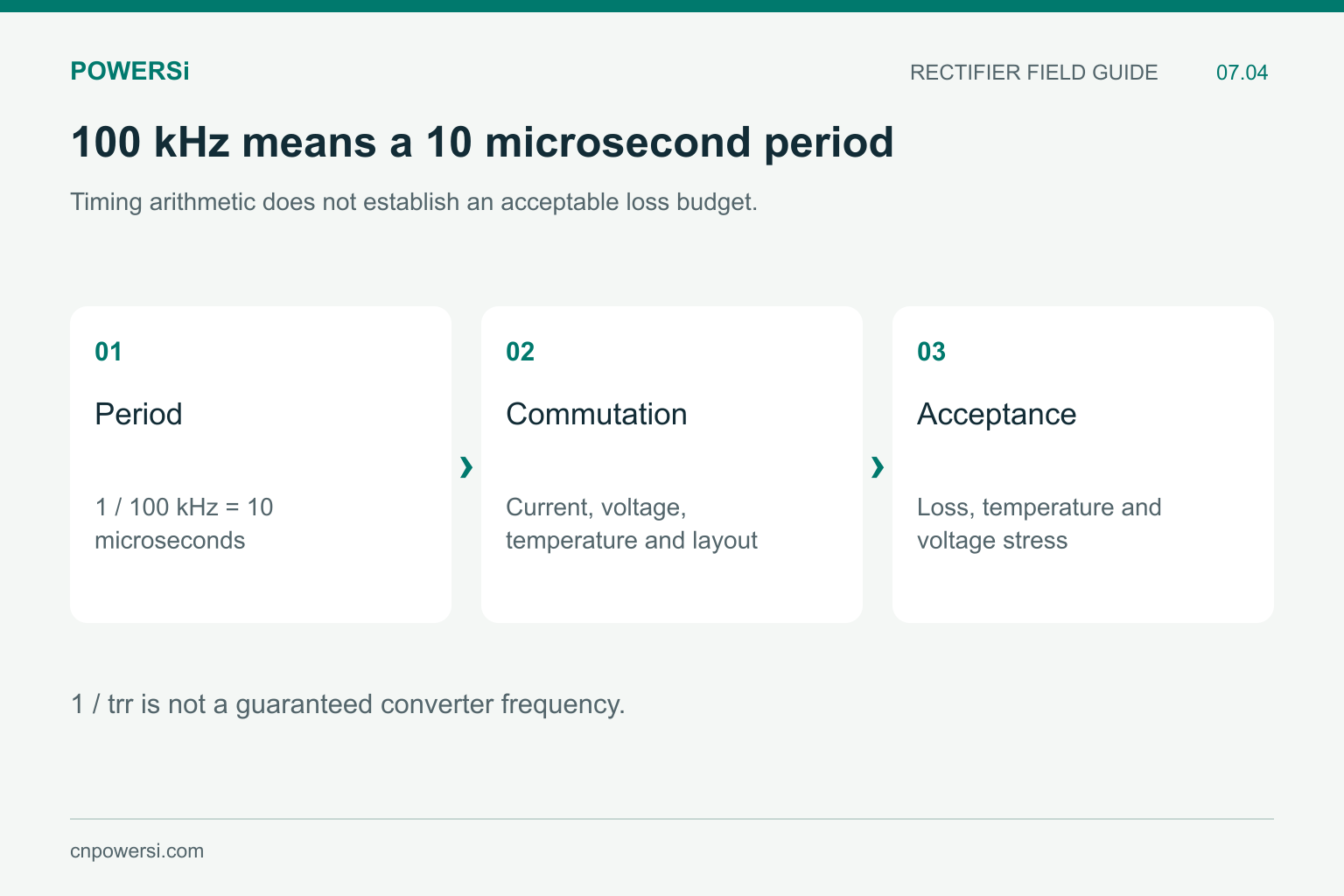
At 100 kHz, one switching period is 10 microseconds. That arithmetic helps describe the circuit, but subtracting a catalog trr from the period does not prove that losses are acceptable. The current at commutation, reverse voltage, temperature and layout also matter.
Likewise, taking 1/trr does not yield a guaranteed maximum converter frequency. Recovery energy and the number of transitions per second contribute to thermal loading. A part may satisfy a timing intuition while still creating unacceptable loss or ringing.
For Schottky devices, review the relevant capacitive behavior rather than assuming there is no switching current. Match the device mechanism to the parameter being compared.
Use the period to describe the circuit, then evaluate actual switching behavior.
Diagnose Heating Before Changing the Technology
If a replacement raises temperature, compare the original and candidate in the same assembly and operating condition. Check conduction loss, actual reverse stress, current pulses, cooling contact and switching waveforms. A poor mounting interface can resemble an electrical selection problem.
If ringing increases, inspect the commutation loop and measurement setup as well as the diode. Probe connection and circuit parasitics can change what is observed. Replacing a diode with a faster part without examining the circuit may not solve the original problem.
Keep the test objective specific: acceptable temperature at a defined load, controlled overshoot, or a measured efficiency target. This gives the buyer a qualification outcome instead of another loosely defined speed label.
Write the Circuit Role Into the RFQ
An effective inquiry identifies the reference designator or diode position, original full part number, blocking requirement, current waveform, switching conditions and cooling arrangement. If an alternate is proposed, retain the original requirements while evaluating the candidate.
Avoid a BOM description that says only “fast diode, same package.” It leaves too much room for an electrically different part that happens to fit the board.
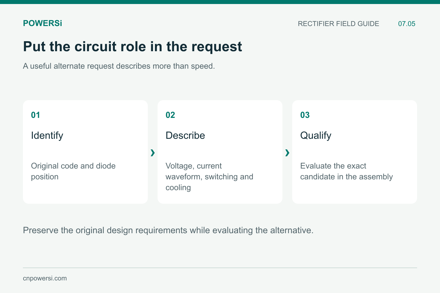
A circuit-specific request reduces ambiguity in substitution.
Key Takeaways
- Classify the diode position before choosing a speed category.
- Line rectifiers still require surge, pulse-current and thermal checks.
- High-frequency suitability depends on dynamic conditions, not trr alone.
- Investigate the complete assembly when heating or ringing changes.
Conclusion
The practical distinction between line-frequency and high-frequency rectifiers is the stress imposed at a specific circuit position. Capture that stress in the purchasing request and qualify the exact candidate in the intended assembly.
Explore POWERSi rectifier products or send the circuit position, original part number and operating waveform to [email protected].
FAQs
Does a switching power supply need fast diodes everywhere?
No. The line-input bridge and the high-frequency converter can impose different waveforms and selection requirements.
Can a line rectifier overheat at 50 or 60 Hz?
Yes. Pulsed current, startup surge, losses and inadequate cooling can still create excessive temperature.
Can I identify switching speed from the package?
No. The package describes mechanical form and contributes to thermal behavior; it does not establish recovery performance.
Is 1/trr the maximum usable frequency?
No. Switching conditions, energy loss, temperature and circuit behavior must also be evaluated.
What should I send when requesting an alternate?
Provide the original full code, circuit position, voltage and current waveforms, switching conditions and mounting arrangement.


