 Skip to content
Schottky Diodes for Low-Voltage, High-Current Rectification: When They Fit
Last Updated: 2026-09-23
Quick Answer
Schottky diodes for low-voltage, high-current rectification are attractive when their forward drop and switching behavior reduce losses within the design’s voltage and thermal limits. They are not mandatory in every circuit. Compare hot reverse leakage, current waveform and cooling, and consider synchronous rectification when its added complexity is justified.
In a low-voltage output, a few tenths of a volt across a rectifier can consume a noticeable share of the available power. As current rises, the heat associated with that drop becomes harder to remove. This makes Schottky technology a useful candidate, but a selection still needs more than a low VF headline.
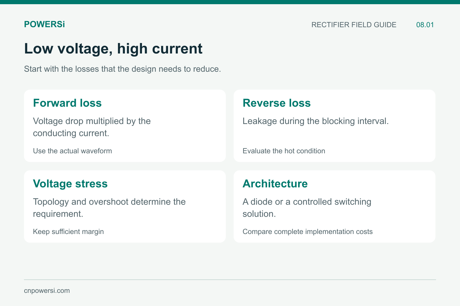
A low forward drop is one part of the decision.
Calculate the Forward-Loss Opportunity
For a simplified constant-current interval, average conduction loss is approximately VF × IF × conduction duty. Consider two hypothetical diodes carrying 20 A for half of each cycle. At a fixed 0.9 V drop, average conduction loss is 9 W. At 0.5 V, it is 5 W. The difference is 4 W for that single diode under those assumptions.
These are teaching values, not POWERSi product ratings or a guaranteed efficiency improvement. Actual forward voltage changes with current and temperature, and a bridge has a different conduction path from a single secondary diode.
Use the actual waveform for a more detailed estimate. The purpose of the first calculation is to establish whether forward loss is a material design issue before comparing candidate parts.
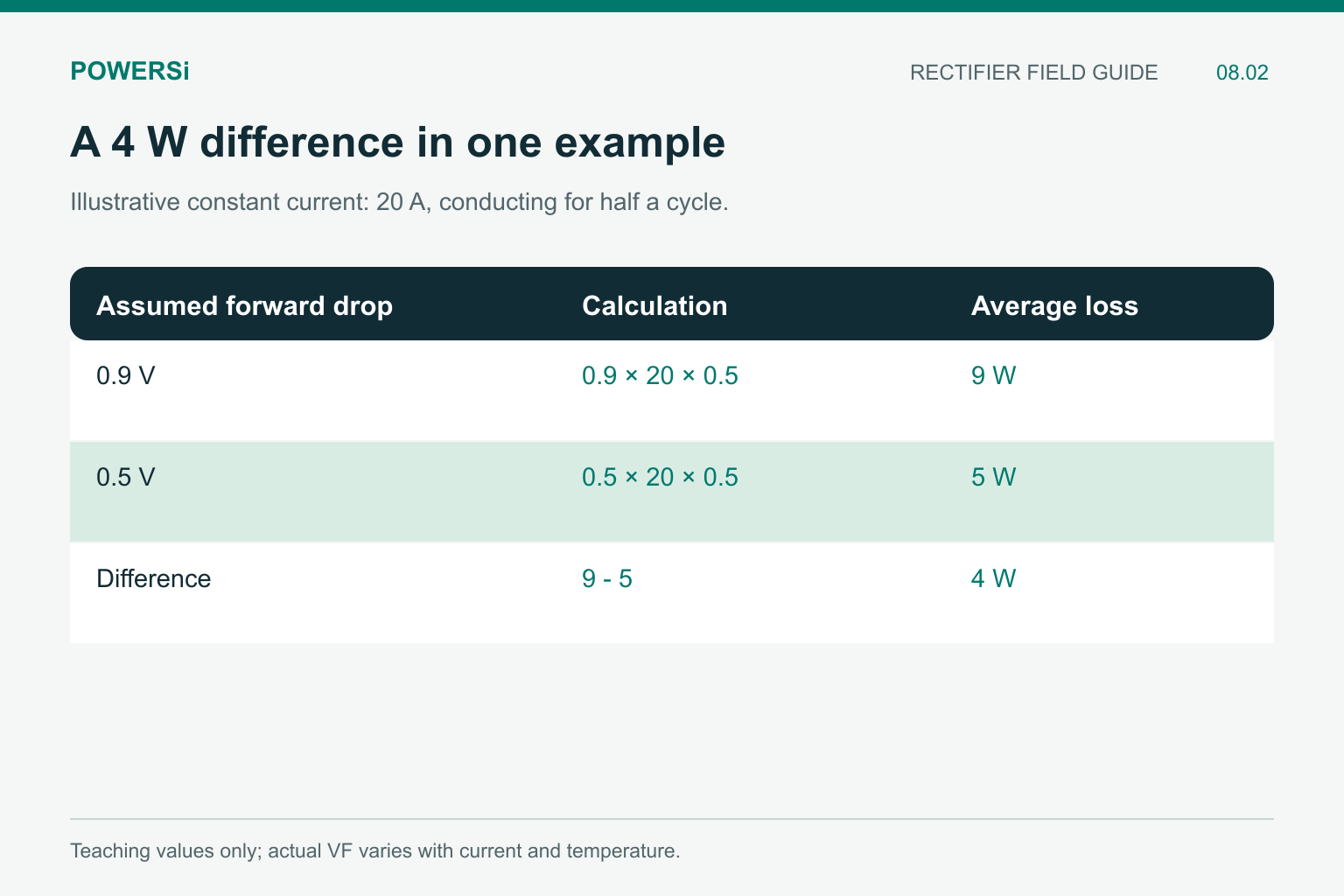
The example shows a loss opportunity, not a specific product rating.
Compare Like-for-Like Forward Voltage
A low typical VF measured at a small current cannot be ranked directly against a maximum value at a much higher current. Keep current, junction temperature and value type attached to each number.
For example, POWERSi MBR60200PT specifies VF of 0.95 V maximum at IF = 30 A and Tj = 25 °C. At IF = 30 A and Tj = 125 °C, the listed 0.76 V value is typical. Neither value establishes its loss at an unrelated operating current, and the typical number is not a guaranteed maximum.
This 200 V device illustrates how to read a silicon Schottky specification. It is not a blanket recommendation for every low-voltage output. A candidate’s voltage class, connection and thermal arrangement must fit the particular design.
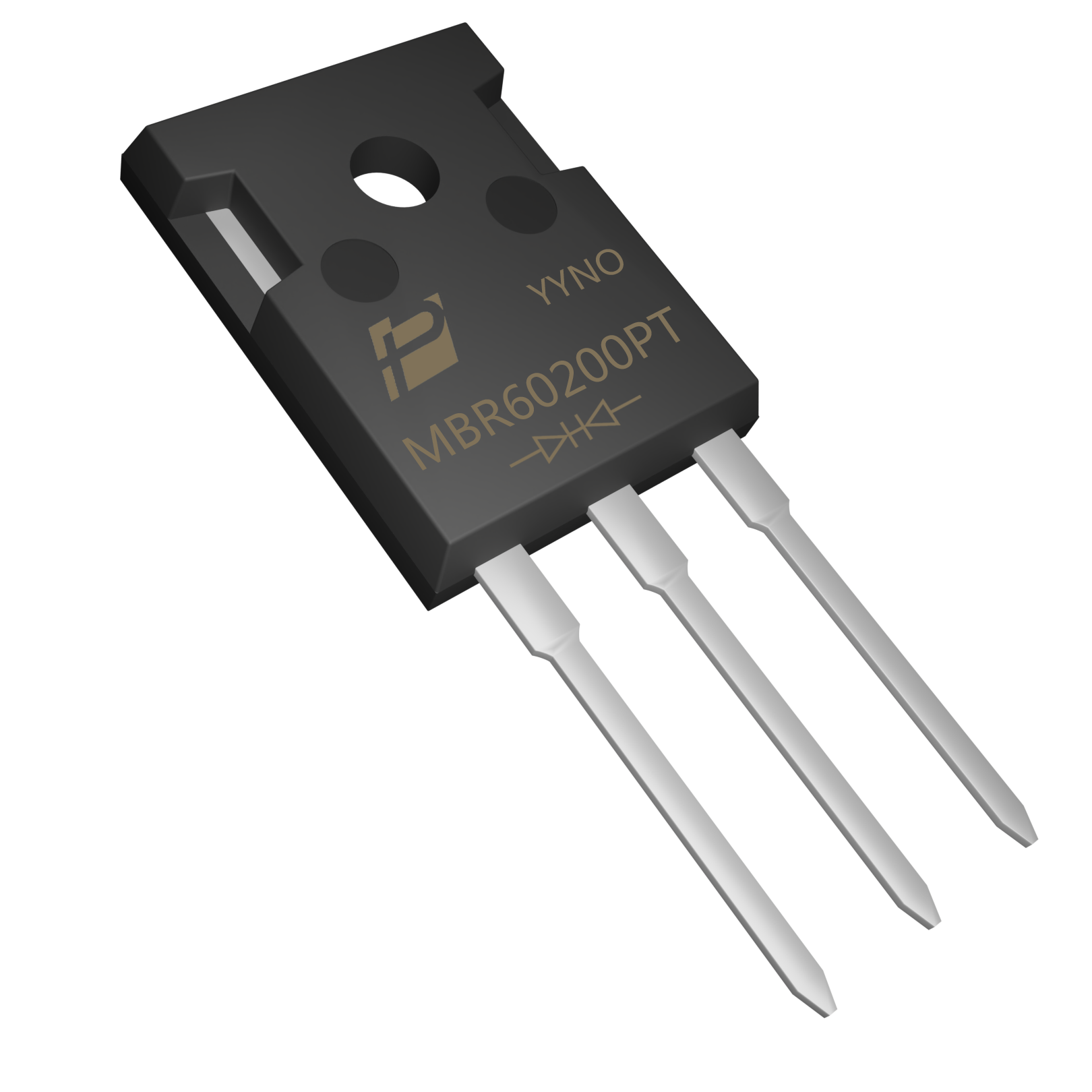
MBR60200PT provides a concrete example of conditioned forward-voltage entries.
Include Hot Reverse Leakage
During the blocking interval, reverse leakage contributes power loss. For a simplified constant reverse voltage, that contribution is approximately VR × IR × blocking duty. Temperature-dependent leakage can erode a forward-loss advantage, particularly when cooling is constrained.
A useful comparison therefore includes both the conducting and blocking parts of the cycle. Nexperia’s discussion of thermal runaway in Schottky rectifiers explains the interaction between leakage, heating and thermal stability. The complete operating point matters more than either a room-temperature leakage value or a minimum forward drop alone.
Do not combine values from different temperatures into a single apparently precise loss total. Use a consistent thermal estimate and evaluate the hot operating condition.
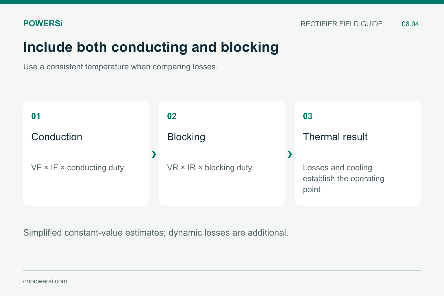
Hot leakage can change the value of a forward-loss improvement.
Keep Enough Reverse-Voltage Capability
The diode’s reverse voltage is set by its position in the circuit. Transformer-secondary arrangements, leakage inductance and switching overshoot can make that stress different from the nominal output voltage.
Choosing a lower voltage class solely to obtain a lower forward drop can remove needed margin. Define the stress envelope first, including relevant transients and tolerances, then compare electrically suitable candidates.
A higher rating is not automatically the best choice either. Its other characteristics may differ. Procurement should preserve the approved voltage requirement rather than optimizing one catalog column in isolation.
Compare the Alternatives
| Option | Why it may fit | What still needs evaluation |
|---|---|---|
| Silicon Schottky diode | Forward-loss and dynamic behavior suited to many lower-voltage positions | Hot leakage, voltage stress and heat removal |
| PN recovery rectifier | A suitable balance of blocking, leakage and switching characteristics | Recovery behavior and conduction loss |
| Synchronous rectification | A controlled MOSFET path can reduce conduction loss in suitable designs | Controller timing, gate drive, reverse current and implementation cost |
For a MOSFET conducting path, the approximate conduction term is I² × RDS(on), using resistance at the relevant temperature. That term alone omits gate-drive and switching losses. Synchronous rectification is a circuit architecture choice, not a pin-compatible diode substitution.
Likewise, Schottky devices still have capacitance that charges and discharges. The absence of the same minority-carrier recovery mechanism as a PN rectifier does not mean that every transition is lossless.
Set a Measurable Acceptance Target
Before ordering alternatives, define what the change should achieve: lower rectifier temperature at a given load, acceptable efficiency across an operating range, or reduced cooling demand. Compare candidates using the same board, cooling conditions and measurement approach where the circuit permits.
Record performance at the hot operating condition and relevant load points. Keep connection and package checks separate from the loss comparison. A promising electrical result does not approve a different lead arrangement or mounting process.
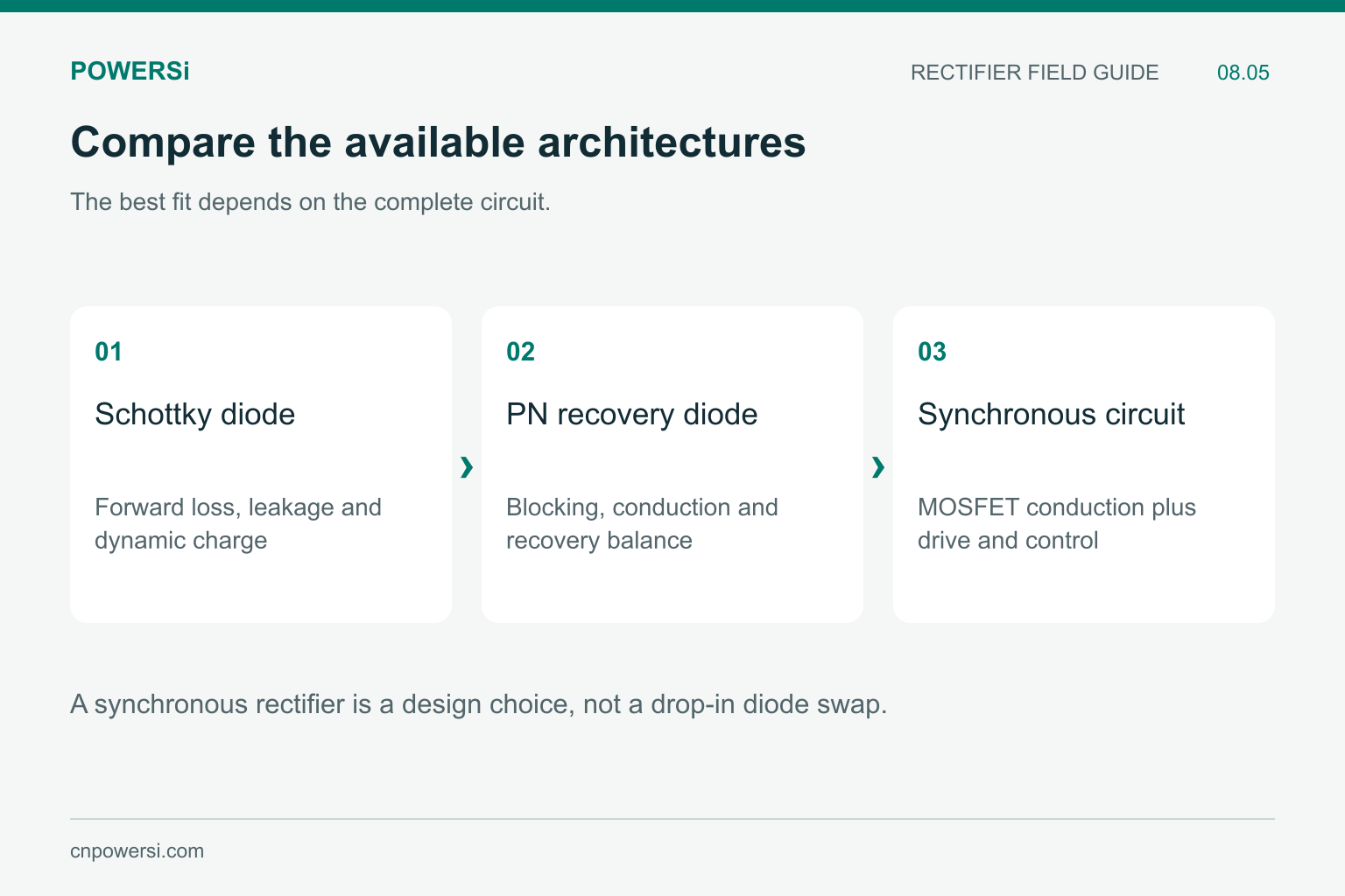
Compare electrical fit and implementation complexity together.
Key Takeaways
- Use the actual current waveform to estimate the forward-loss opportunity.
- Compare hot leakage and thermal behavior as well as VF.
- Establish reverse-voltage requirements before choosing a voltage class.
- Consider synchronous rectification as a design option, not a simple replacement.
Conclusion
Schottky rectifiers can be a strong fit for low-voltage, high-current circuits when their complete loss and thermal behavior meets the design need. The useful question is which device or architecture performs well in the actual circuit, rather than whether one technology is always compulsory.
Browse the POWERSi catalog or send your reverse stress, current waveform and cooling limits to [email protected] for a product inquiry.
FAQs
Must every low-voltage output use a Schottky diode?
No. The right choice depends on loss, leakage, voltage stress, switching behavior, cooling and the circuit architecture.
Is the lowest VF always the most efficient choice?
No. Reverse leakage and dynamic losses can change the total operating-cycle result.
Can I select the voltage rating from output voltage alone?
No. Determine the actual reverse stress at the diode, including topology-dependent voltage and relevant overshoot.
Does synchronous rectification directly replace a diode?
It normally requires a suitable controlled switching arrangement. Timing, gate drive and reverse-current behavior need design work.
What data makes a Schottky comparison useful?
Use matched current and temperature, reverse-voltage stress, blocking duty, current waveform and the actual cooling arrangement.


