Skip to content

Last Updated: November 5, 2026
Key Engineering Takeaways
- Estimate bridge loss from the actual waveform before selecting a heat sink.
- Use a thermal model that matches the manufacturer’s per-junction or whole-bridge definition.
- Validate case temperature and the mounting interface inside the intended enclosure.
Size a bridge rectifier heat sink by estimating worst-case bridge loss, defining the allowable temperature rise, and subtracting the junction-to-case and mounting-interface thermal resistances. Then test the mounted bridge at the highest relevant air temperature inside the enclosure. The package’s current rating alone does not specify the heat sink you need.
Map the heat path
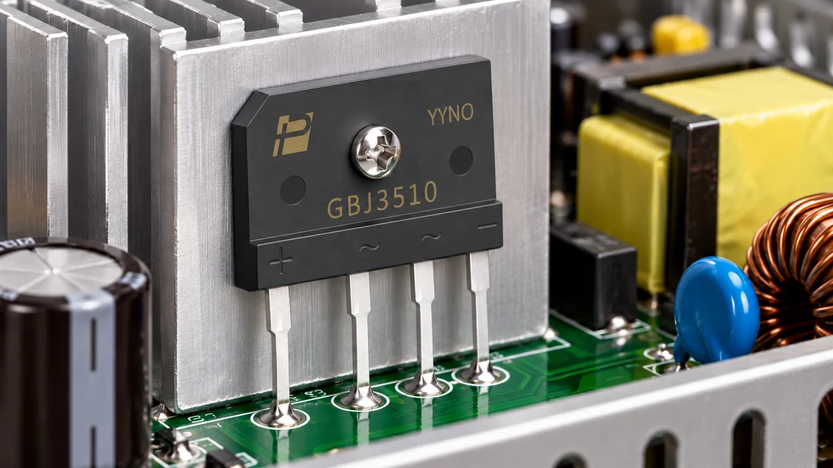
Heat travels from the conducting junctions through the package to the case, across the thermal interface, through the heat sink and into the surrounding air. Each step consumes part of the allowed temperature rise. A thick interface pad, uneven mounting surface, restricted airflow or nearby hot components can make a heat sink perform worse than its catalog value.
A bridge has multiple junctions and two are in the current path at a time. Its thermal-resistance definition may refer to a single junction or a particular bridge test arrangement. Read the manufacturer’s definition carefully before using total bridge loss with a published junction-to-case figure. Do not mix per-junction loss with an effective whole-bridge thermal resistance.
| Input | How to obtain it | Why it matters |
|---|---|---|
| Bridge loss | Use the actual current waveform and temperature-dependent VF characteristics; include both conducting junctions | Sets heat to remove |
| Design junction limit | Select a target below the rated maximum using engineering margin | Determines available temperature rise |
| Local ambient | Measure or specify worst-case air at the heat sink inside the cabinet | Room temperature can underestimate the starting temperature |
| Junction-to-case and interface | Use the correct device thermal model and the installed interface specification | These consume part of the thermal budget |
| Heat-sink performance | Check the supplier’s orientation, airflow and mounting conditions | Catalog °C/W values are condition dependent |
Estimate loss before choosing metal
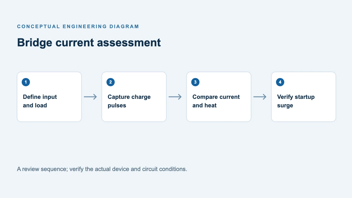
For a simplified constant-drop estimate, bridge conduction loss is approximately 2 × VF × average conducting-path current, because two junctions conduct in series. With a capacitor-input circuit, use the measured or simulated charging pulses and the forward curve at relevant temperatures for a more realistic result. A single typical VF point is not a worst-case loss guarantee. Include additional losses if they matter in the chosen circuit and operating mode.
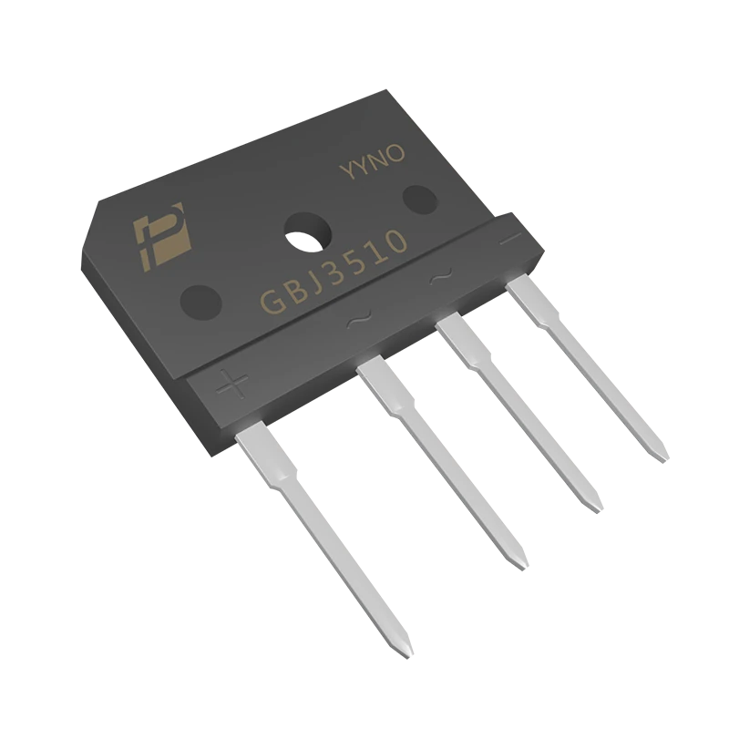
The GBJ3510 product page lists 35 A with a heat sink at a 110 °C case temperature, while its linked version 2.0 datasheet lists 35 A with a heat sink at 92 °C. Their published junction-to-case thermal resistance values also differ: 1.0 °C/W on the product page and 0.8 °C/W in the datasheet. Ask POWERSi to confirm the controlled ratings, thermal model and applicable drawing for the exact ordering code before design release. The headline current rating alone cannot establish operation without a heat sink or at an arbitrary mounting temperature.
A thermal-budget example
For a preliminary calculation, the series thermal model described in ST’s rectifier thermal-management note can be written as:
RθSA ≤ (TJ target − TA) / P − RθJC − RθCS
Here RθSA is sink-to-ambient resistance; RθJC and RθCS represent the junction-to-case and case-to-sink paths in a consistent model. All resistances are in °C/W, temperature in °C and P in watts. For a bridge, first ensure that the resistances and power correspond to the same effective junction and heat-flow model.
Imagine a hypothetical equivalent thermal model—not GBJ3510 product data or a measured assembly—with a 120 °C junction target, 50 °C local ambient, 40 W total bridge loss, 0.7 °C/W effective junction-to-case resistance and 0.3 °C/W case-to-sink resistance. The maximum preliminary sink-to-air resistance is (120 − 50) / 40 − 0.7 − 0.3 = 0.75 °C/W. A sink rated lower than this under the actual mounting and airflow conditions is a candidate. If the result is zero or negative, improve cooling, lower loss or change the design; choosing a larger fin alone cannot repair an impossible upstream thermal budget.
This example is not a GBJ3510 heat-sink recommendation. Establish an appropriate multi-junction model from the current datasheet or manufacturer, then check transient and steady-state behavior and allow for component and production variation.
Mount and measure the complete assembly
Use the approved surface finish, flatness, interface material and fastener method. Apply the manufacturer’s torque specification and check whether electrical insulation is required for the entire equipment. A terminal-to-case dielectric test rating is not a system insulation approval; review clearances, creepage and safety requirements for the end use.
At maximum specified local ambient, run the equipment at relevant low-line and high-load conditions until temperature stabilizes. Measure air near the sink, the specified case point, sink and accessible terminals. Compare measured temperatures against the current derating curve and use the correct thermal model to estimate junction temperature. Repeat with the intended enclosure, fan condition and neighboring loads. Also investigate start/stop and fault pulses separately; steady-state heat-sink sizing does not prove surge capability.
A mounting-interface acceptance check
The earlier KBPC, GBJ and GBU package guide compares mechanical interfaces. Here the question is whether a chosen interface actually transfers the heat in production.
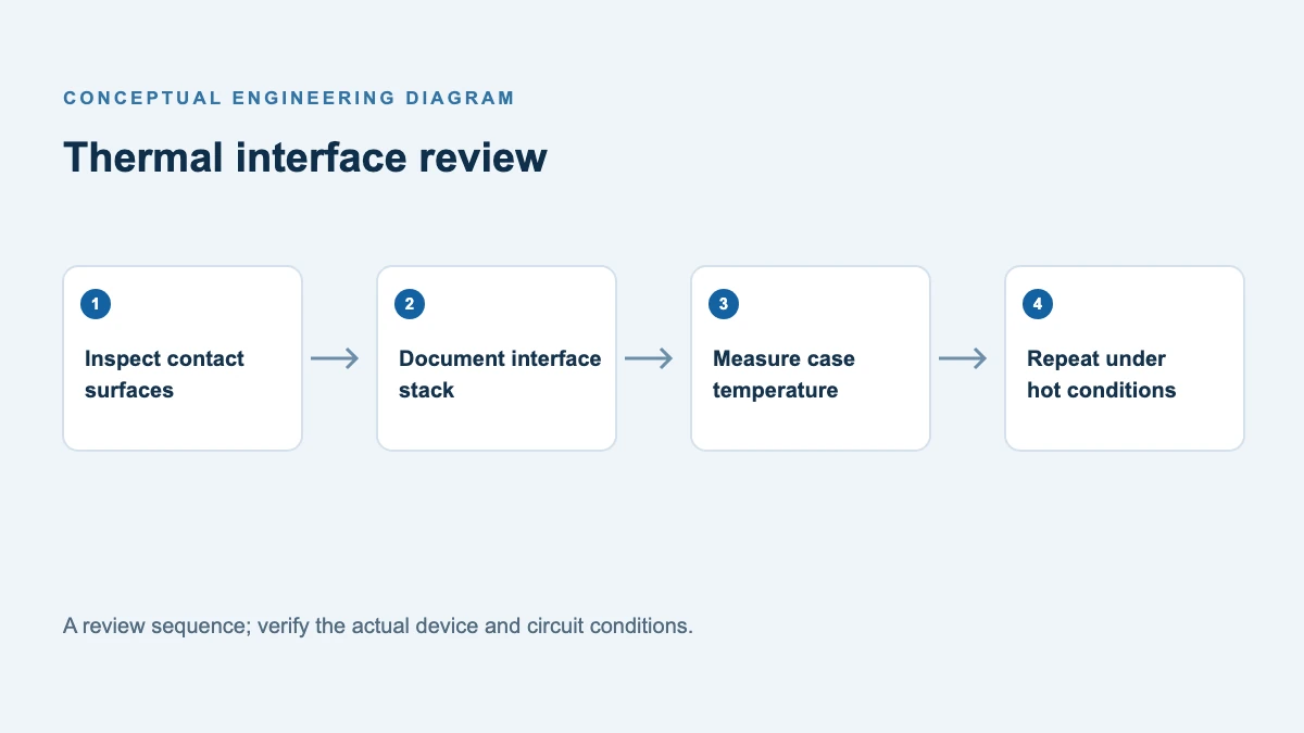
- Before assembly: confirm the exact outline and lead variant, unobstructed hole alignment, flat clean contact surfaces and specified insulation. Select a controlled interface material and thickness; do not assume that more paste or an arbitrary pad improves performance.
- During assembly: apply the specified interface process and torque using a calibrated tool. Support the leads so board placement does not pull the body away from the sink. Inspect contact and avoid mechanically stressing the package. Use the exact part’s current drawing and torque limits.
- Compare repeatable prototypes: run at the same measured power and stable local air temperature. Record the location of the case and sink sensors near the contact, interface material and torque. A persistent increase in case-to-sink temperature difference at comparable dissipation can indicate poor contact, but sensor placement and lateral spreading also affect the reading; investigate rather than treating ΔT/P as a directly guaranteed interface resistance.
- Release the process: set acceptance limits using the design’s thermal model and validated measurement uncertainty. Recheck after handling and thermal cycling as appropriate. Track interface material, application method, torque and sink orientation in the assembly documentation.
Choose the package as part of the cooling system
A candidate sink must physically fit the board, leads and installation method. Confirm that its published thermal resistance assumes the intended airflow, fin orientation and temperature rise; measured system performance takes precedence over a catalog value used outside its test conditions. Review the GBJ3510 bridge rectifier details and its controlled datasheet. For a GBJ3510 application, send POWERSi the waveform, available mounting area, local ambient, cooling and target current so the exact part and interface can be reviewed.
FAQ
Is the bridge case temperature equal to junction temperature?
No. Junction temperature is higher by an amount related to junction loss and the junction-to-case thermal path. The specific bridge thermal model determines the calculation.
Can thermal paste replace a heat sink?
Paste improves contact between surfaces; it does not provide the sink-to-air surface area required to remove significant heat. Both interface and sink must be evaluated.
Does a larger current rating remove the need for thermal testing?
No. Current ratings are conditional. Loss, ambient, mounting and airflow still set the operating temperatures in the final equipment.
Why measure air temperature inside the enclosure?
The air around the heat sink can be warmer than the room. Use the relevant local operating temperature and airflow when evaluating the assembled equipment.