 Skip to content
ESS Bidirectional DC/DC: Rectification in Both Directions
Last Updated: 2026-10-13
Quick Answer
Bidirectional ESS converters need controlled current paths for both charging and discharging. A passive diode cannot provide that control by itself. Identify active rectification, reverse-conduction intervals and any separate clamp or auxiliary diodes, then evaluate voltage stress, commutation, temperature and protection across both power directions and transitions.
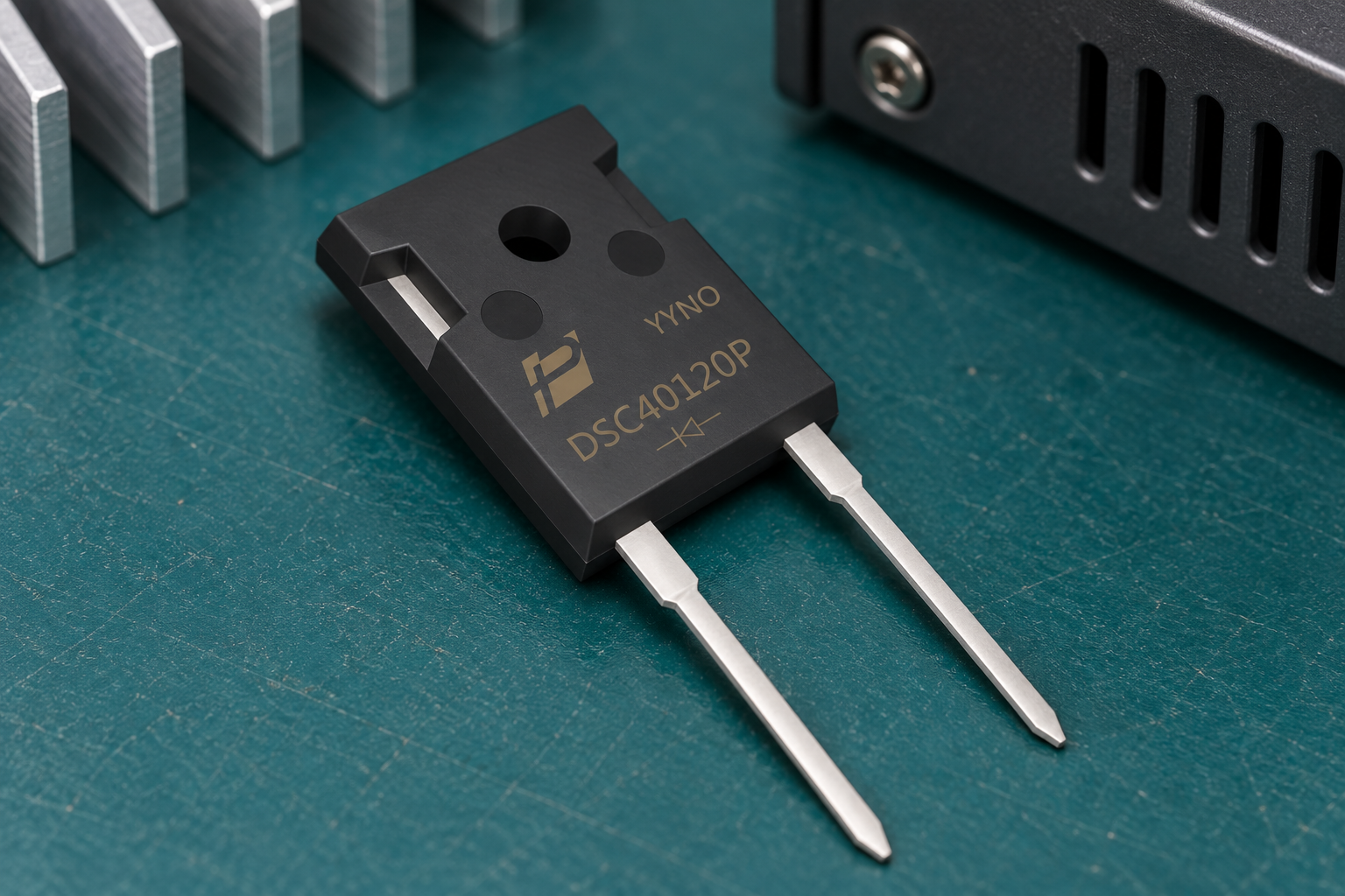
Product scene based on the supplied DSC40120P reference; application suitability is evaluated separately.
Distinguish Active Rectification From a Passive Diode
The converter architecture defines how power reverses. A dual active bridge uses controlled switching bridges on both sides of an isolation transformer; changing the control relationship changes the power flow. A passive diode placed in the main path cannot independently reproduce that function.
TI’s TIDA-010054 dual active bridge reference design illustrates bidirectional conversion for charging and energy-storage applications. Use such an architecture example to identify device roles, not to assume that a named diode appears in its bill of materials. Begin with the actual system schematic and control strategy.
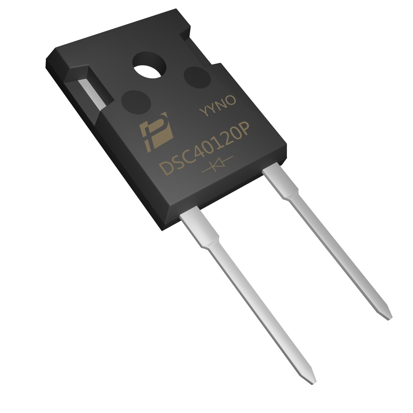
Supplied DSC40120P product reference; no system-level suitability or qualification is implied.
Keep Discrete Diode Roles Explicit
Discrete diodes can still serve clearly defined functions around an active converter. An auxiliary supply, a particular clamp circuit or a unidirectional branch may have a legitimate diode position. Whether one exists, and what it must withstand, depends on the actual topology.
POWERSi DSC40120P is a 1200 V SiC Schottky diode in a two-lead TO-247AC package according to its supplied documentation. It is shown as a discrete-device example, not as an active-bridge replacement or a confirmed ESS component selection. Its blocking class does not establish compatibility with every battery or DC-link voltage, and its current direction remains a diode function.
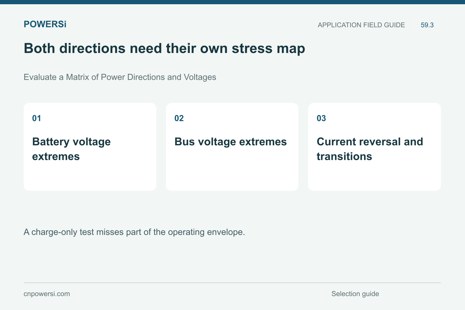
Both directions need their own stress map.
Evaluate a Matrix of Power Directions and Voltages
A charge-only test misses part of the operating envelope. Evaluate the relevant combinations of battery voltage, bus voltage, power level and direction. Include the interval near zero power and the transition between charge and discharge where the control behavior changes.
| Operating point | Device-level question |
|---|---|
| Charging | Which devices conduct and commutate? |
| Discharging | Does the hottest device or current path change? |
| Light load | Are soft-switching conditions maintained? |
| Direction reversal | How are transient current and stored energy controlled? |
| Fault or shutdown | Where can current continue after the command changes? |
Do not infer identical stress from nominal circuit symmetry. Voltage ratio, dead time, parasitics and control choices can shift the loss distribution.

Illustrative application scene; not a customer installation or a measurement result.
Include Reverse Conduction and Protection
During dead time, the available reverse-conduction path depends on the switching device technology and circuit arrangement. Identify that path before proposing an external diode. An added device can change capacitance and commutation without carrying current in the way a simplified sketch suggests.
Trace stored energy during startup, shutdown and abnormal events. Determine which control or protection element interrupts the current and what voltage appears across each device. A blocking-voltage rating alone cannot establish fault survival. Use the application’s defined abnormal-event tests and avoid transferring a surge claim from a different waveform or initial temperature.
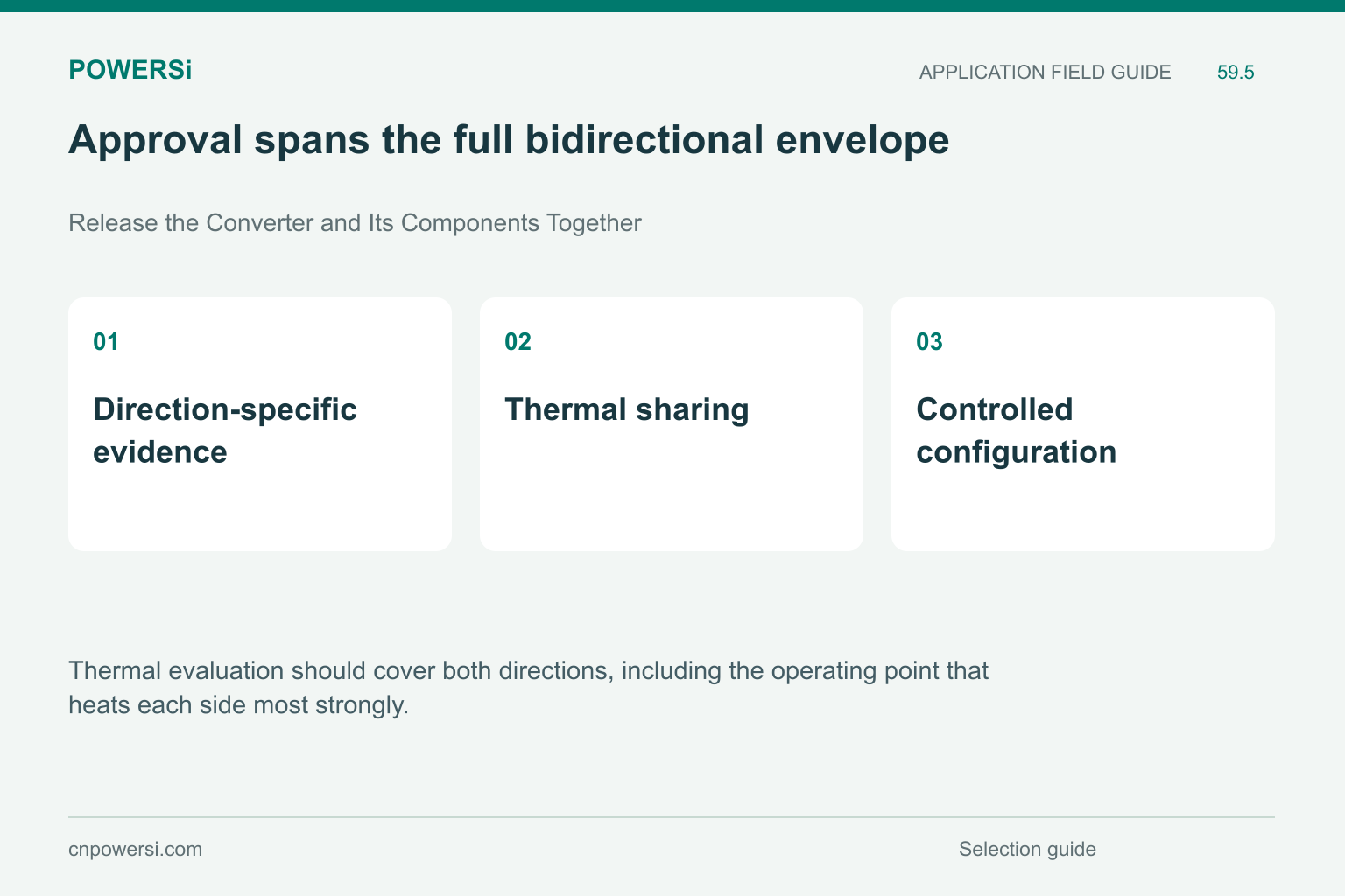
Approval spans the full bidirectional envelope.
Release the Converter and Its Components Together
Thermal evaluation should cover both directions, including the operating point that heats each side most strongly. Keep interface materials, cooling conditions and sensor locations consistent. A cooler measured case does not necessarily prove a cooler junction when the package or heat path changes.
For a POWERSi diode inquiry, identify the exact passive-device position within the ESS converter and provide its waveforms in every relevant state. Evaluate that candidate within the complete control and protection configuration. Release it with traceable evidence and a clear application boundary rather than describing a discrete diode as a universal bidirectional rectifier.
Key Takeaways
- Bidirectional power needs controlled paths.
- Both directions need their own stress map.
- Approval spans the full bidirectional envelope.
Conclusion
Map the active power path and each passive diode position separately. Share the complete operating-state requirements with POWERSi before selecting an ESS diode candidate.
FAQs
Can one passive diode implement controlled bidirectional conversion?
No. Controlled switching paths are required for the intended power-flow function.
Are discrete diodes always absent from a bidirectional converter?
No. Defined auxiliary, clamp or other unidirectional paths may still use them.
Is DSC40120P presented as a dual active bridge replacement?
No. It is a discrete SiC product example for a separately defined diode position.
Is testing at one battery voltage enough?
No. Evaluate the relevant voltage ratios, directions and transitions.
Why inspect shutdown current paths?
Stored energy and device conduction paths can sustain current after control commands change.


