 Skip to content
Looking for a second source for RHRP15120? POWERSi DSE15H12 is a candidate for evaluation. Both are rated at 1200 V and 15 A and use a two-lead TO-220AC package. Those similarities make an initial comparison useful; recovery behavior, thermal margin and mechanical fit determine whether the candidate suits your circuit.
This guide compares the published specifications and explains what to check before approving a replacement. It gives engineers a path from datasheet review to bench testing, and purchasing teams a clear basis for requesting samples and qualification records.
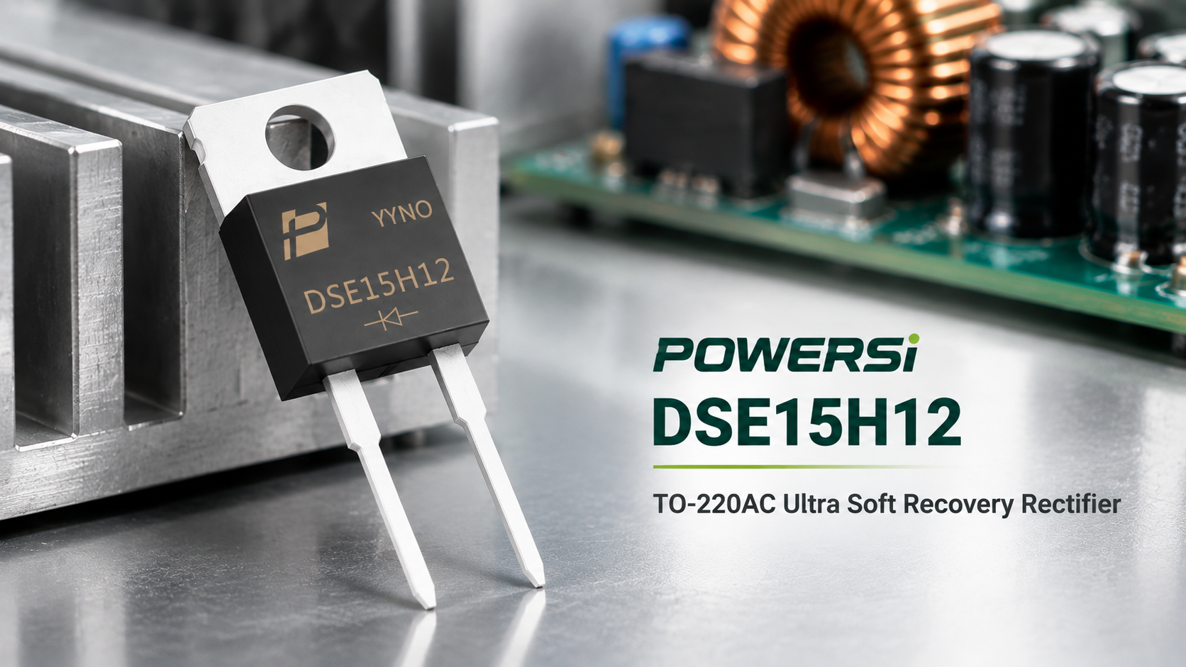
Figure 1. POWERSi DSE15H12 ultrafast soft-recovery rectifier.
onsemi RHRP15120: Discontinued Status and Replacement Options
The onsemi RHRP15120 is included in Product Discontinuance Notice PD25829XB, issued on October 6, 2023. The notice specifies April 6, 2024 as the last-time-buy date and October 6, 2024 as the last-ship date. Remaining inventory may still be available, so buyers should verify product authenticity, traceability and availability.
For designs using RHRP15120, POWERSi DSE15H12 is a candidate for second-source evaluation. Although both devices share the same nominal voltage and current ratings and package designation, their electrical, thermal and mechanical characteristics must be compared under the relevant operating conditions before substitution.
The following sections compare the published specifications and outline the qualification checks required to assess DSE15H12 for your application.
Why evaluate DSE15H12?
DSE15H12 specifies a maximum forward voltage of 2.1 V at IF = 15 A and Tj = 25°C. RHRP15120 specifies 3.2 V at IF = 15 A and TC = 25°C. This difference merits testing in designs sensitive to conduction loss, but does not establish a system-efficiency improvement.
Thermal resistance also matters: DSE15H12 lists 2.0°C/W junction-to-case, while RHRP15120 lists a maximum of 1.5°C/W. Evaluate forward drop, recovery behavior and heat flow together.
Explore DSE15H12 product information and datasheet access
Key specifications at a glance
The comparison below retains the stated test conditions.
| Parameter | POWERSi DSE15H12 | onsemi RHRP15120 |
|---|---|---|
| Repetitive peak reverse voltage | 1200 V | 1200 V |
| Current rating | 15 A; refer to case-temperature derating | 15 A at TC = 140°C |
| Package | TO-220AC, two leads | TO-220AC, two leads |
| Forward voltage, max. | 2.1 V at IF = 15 A, Tj = 25°C | 3.2 V at IF = 15 A, TC = 25°C |
| Reverse leakage, max. | 10 μA at VR = 1200 V, Tj = 25°C | 100 μA at VR = 1200 V, TC = 25°C |
| Reverse recovery time, max. | 60 ns at IF = 0.5 A, IRM = 1 A, IRR = 0.25 A, Tj = 25°C | 65 ns at IF = 1 A 75 ns at IF = 15 A Both: dIF/dt = 100 A/μs, TC = 25°C |
| Junction-to-case thermal resistance | 2.0°C/W | 1.5°C/W, max. |
| Junction temperature range | −55°C to +175°C | −65°C to +175°C |
| Non-repetitive surge current | 200 A; 8.3 ms single pulse | 200 A; 60 Hz single-phase half-wave |
Tj denotes junction temperature; TC denotes case temperature. Equal ratings do not imply equal test conditions. For RHRP15120, 65 ns applies at 1 A; the maximum at 15 A is 75 ns.·
What the electrical differences mean
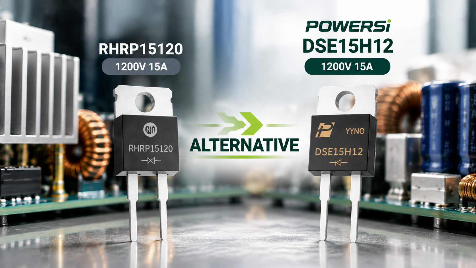
Figure 2. DSE15H12 is a candidate for evaluation; suitability depends on circuit validation.
Measure conduction loss under the actual waveform
Maximum forward voltage is a specification limit, not the operating voltage of every sample. Measure diode voltage and current at matched load and temperature, then average their product over the switching cycle. To assess system efficiency, also record input and output power and any change in losses in the associated switching devices.
Do not rank recovery performance by time alone
The 60 ns DSE15H12 value uses IF = 0.5 A. The 65 ns RHRP15120 value uses IF = 1 A; its 15 A value is 75 ns. These different test points do not establish which device produces lower loss in your circuit.
Compare peak reverse recovery current, recovery charge, voltage overshoot and ringing on the same board. Check stress on the associated switch as well. If the design relies on recovery charge or avalanche capability, request the corresponding candidate-device data; an unspecified characteristic is not a confirmed match.
Include thermal resistance in the loss assessment
For a steady-state estimate, junction-to-case temperature rise is approximately device dissipation multiplied by junction-to-case thermal resistance. At an assumed 10 W, the listed values give about 20°C for DSE15H12 and 15°C for RHRP15120. This is an illustrative calculation, not a measured comparison: actual losses may differ. Include the interface material, heatsink and ambient conditions in the thermal assessment.
Check more than the TO-220AC package name
A shared package designation narrows the search, but does not establish assembly compatibility. Confirm polarity, tab connection, lead spacing and mounting dimensions against the mechanical drawings.
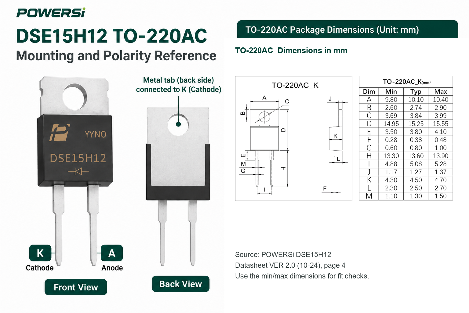
Figure 3. DSE15H12 polarity and package dimensions.
Confirm polarity and the metal-tab connection
For DSE15H12, with the marked face toward you and the leads pointing down, the left lead is the cathode (K) and the right lead is the anode (A). The metal tab connects to the cathode. If the heatsink must be electrically isolated, check the insulating pad and mounting hardware and include interface thermal resistance in the temperature assessment.
Compare tolerance ranges, not just nominal sizes
Review lead cross-section, body thickness, lead length, mounting-hole diameter and hole position. DSE15H12 has a nominal lead pitch of 5.08 mm with a specified range of 4.88–5.28 mm. Verify the assembly against the drawing tolerances rather than a product photograph.
Also check cold-temperature requirements. The specified junction-temperature lower limit is −55°C for DSE15H12 and −65°C for RHRP15120. A project requiring operation below −55°C must resolve this difference before qualification proceeds.
How to qualify a replacement sample
Start with a repeatable baseline. Keep the PCB, drive settings, load, cooling hardware and measurement method consistent so that changes can be attributed to the device.
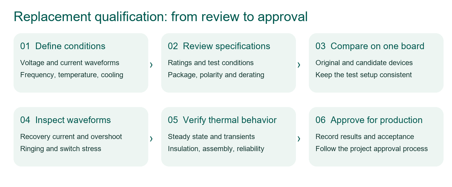
Figure 4. A six-stage qualification workflow, from operating conditions to production approval.
1. Define operating conditions and acceptance limits
Record topology, operating voltage, current waveform, switching frequency, ambient temperature and cooling method. Set limits for overshoot, temperature rise, efficiency and noise. Purchasing records should identify the full orderable part number, sample lot and required project documentation.
2. Establish a same-board comparison
Capture RHRP15120 baseline waveforms, input/output power and case temperature before fitting DSE15H12 samples. Keep probe locations, connections and load settings consistent. Cover the required input-voltage, load and temperature combinations, including startup, shutdown and load transients.
3. Review differences and approve the final configuration
Compare recovery current, reverse voltage, switch stress and steady-state temperature against the acceptance limits. If the snubber, drive settings or cooling arrangement changes, document the change and repeat affected tests. Complete the required reliability, assembly and production-approval steps after sample evaluation.
Keep a concise qualification record: datasheet revisions, sample lots, test setup, key waveforms, temperature results, deviations and approval. This gives engineering and purchasing a shared basis for a sourcing decision.
Frequently asked questions
Can DSE15H12 directly replace RHRP15120?
It can enter the evaluation process. Matching voltage, current and package names alone does not establish a drop-in replacement. Verify electrical, switching, thermal and mechanical compatibility in the target circuit.
Why check derating when both devices are rated at 15 A?
The rating depends on specified temperature and cooling conditions. Use actual case temperature, current waveform and the thermal path to determine the operating range; 15 A is not a universal free-air rating.
Does lower leakage at 25°C predict high-temperature performance?
No. It describes one test point. For high-temperature, high-reverse-voltage or standby-sensitive operation, review the relevant leakage limits and test at the required conditions.
Does the 200 A surge rating allow repeated overloads?
A non-repetitive surge rating does not establish repetitive overload capability. Review pulse shape, duration, starting temperature and repetition before applying it to a load profile.
Can the existing heatsink and insulating pad be reused?
Only if mechanical and thermal checks support reuse. Verify mounting dimensions, tab potential, interface resistance and estimated junction temperature. Revalidate any design changes.
Start a DSE15H12 sample evaluation
Share your existing part number, topology, operating voltage, current waveform, switching frequency and cooling conditions with POWERSi. Include sample quantities and documentation needs. Baseline waveforms and temperature records help focus the discussion on the differences that matter to your design.


