Skip to content

BMS Back-to-Back MOSFETs: Why Schottkys Differ
Last Updated: 2026-11-16
Quick Answer
BMS back-to-back MOSFETs provide a controllable path that can conduct when enabled and block both current directions when disabled, within the circuit’s limits. Opposing series Schottky diodes do not offer that function: one remains reverse biased in either direction. Distinguish bidirectional isolation from passive rectification before selecting protection components.
Illustrative BMS development setting; no specific POWERSi switch or reference design is shown.
Separate Pack Isolation From Rectification
A battery pack may need to accept charge, supply a load and interrupt current under a fault. Those requirements call for controlled operating states. A rectifier diode responds to voltage polarity; it does not provide an independent command to open or close the main current path.
Two Schottky diodes in opposing series orientation block ordinary conduction in both directions, apart from leakage and behavior beyond their permitted blocking conditions. They do not become a low-resistance bidirectional path when a BMS requests charging or discharge. Two diodes in antiparallel are different again: each direction has a forward-conducting diode. That arrangement is not bidirectional isolation either.
Illustrative battery-protection test fixture.
Understand What Back-to-Back MOSFETs Add
Each power MOSFET has a body-diode path that can conduct in one direction when the channel is off. Arranging two suitable MOSFETs back to back opposes those body diodes. With both channels off, a diode path cannot normally carry current all the way through in either direction. With suitable gate drive, both channels can conduct.
The exact connection may use common-source or common-drain arrangements. Gate referencing and controller compatibility differ, so the two drawings must not be interchanged without analysis. TI discusses the principle in Protect Your System From Reverse Current.
The diagram below is a functional state comparison, not a pin-level construction drawing. It intentionally does not prescribe a gate driver, pack voltage or protection threshold.
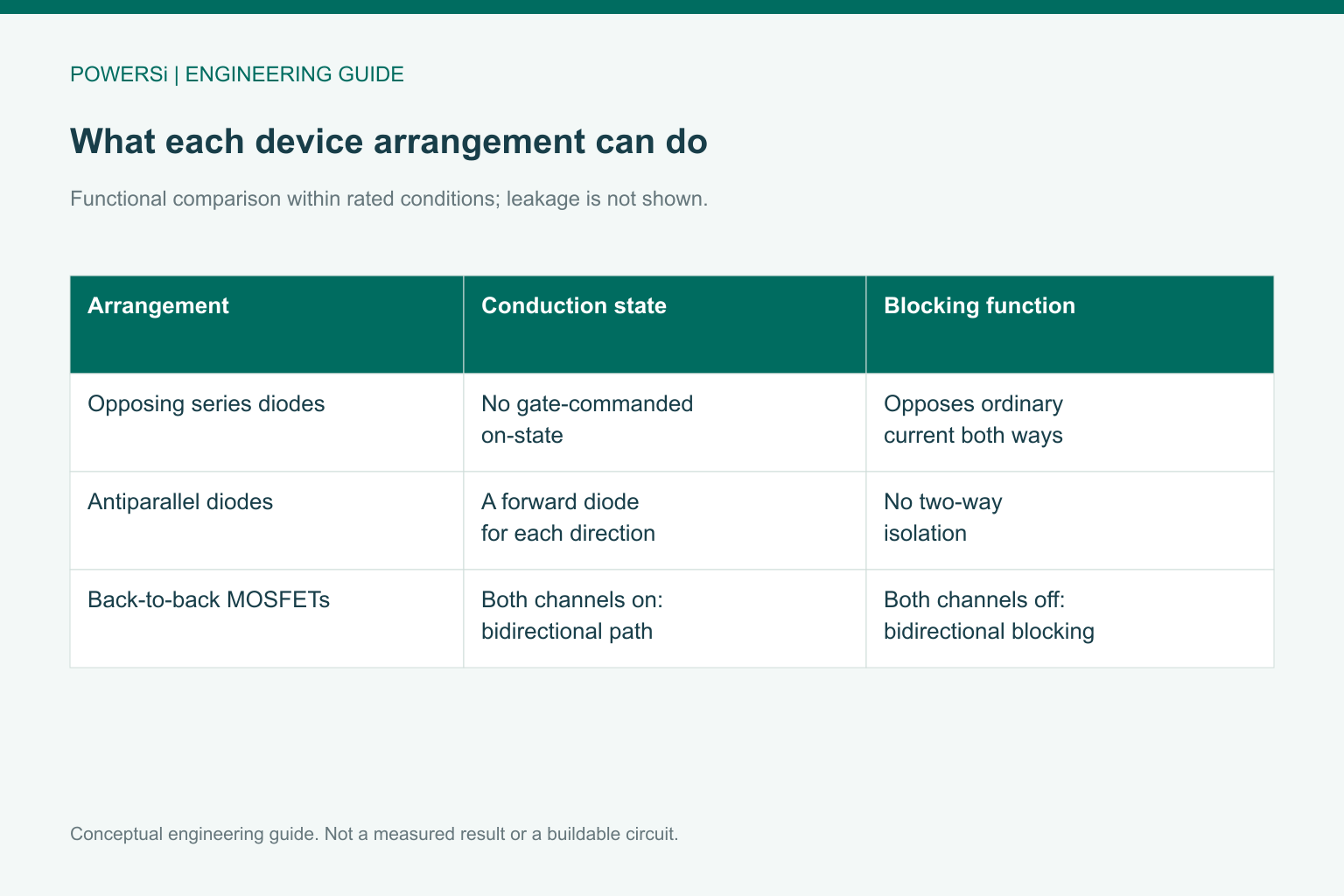
Functional comparison within device limits; not a gate-level construction drawing.
Define Charge and Discharge States Explicitly
A BMS may control charge and discharge switches independently. Turning off one channel can block the undesired direction while the other direction remains possible through a channel and a body diode, depending on the arrangement. That body-diode interval can have substantially greater loss than normal channel conduction.
Build a truth table for the actual controller and topology: normal charge, normal discharge, charge inhibited, discharge inhibited and full isolation. Identify the current path in every row. Do not assume that turning one gate off always means both directions are blocked.
Some controllers are specifically intended to drive independently controlled back-to-back switches. TI’s TPS1210-Q1 documentation provides one architectural example. It is not a universal controller recommendation for every battery voltage or application.
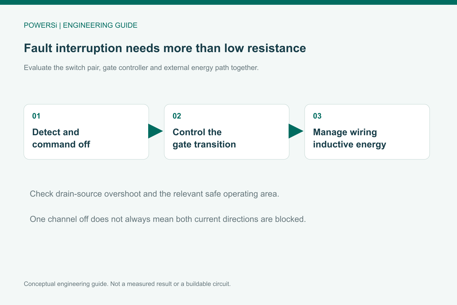
Conceptual engineering guide; no measured performance is shown.
Check Interruption Stress as Well as On-State Loss
During normal conduction, both MOSFETs contribute resistance. At interruption, the circuit must manage energy stored in wiring and load inductance. Evaluate drain-source overshoot, gate behavior and the actual turn-off current; a low on-resistance alone does not establish fault-interruption capability.
Check the relevant safe operating area for precharge, slow turn-on or current-limiting states where a switch simultaneously supports voltage and current. Account for temperature and pulse duration. Back-to-back devices are not galvanic isolation, and real off-state leakage remains.
Verification should include the controller’s supply loss or undervoltage behavior, reconnecting a charger, a charged load-side capacitor and the allowed inductive-load conditions. Select tests from the real fault requirements rather than treating one successful bench disconnection as complete BMS qualification.
Conceptual engineering guide; no measured performance is shown.
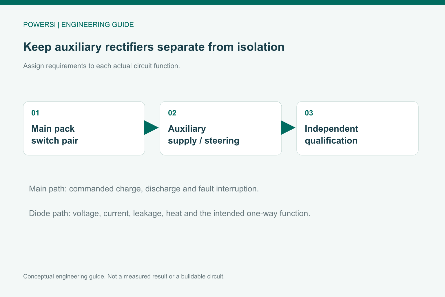
Keep Auxiliary Diodes in Their Proper Roles
Schottky rectifiers may still be useful in auxiliary supply paths, steering networks or other properly rated diode functions around a battery system. Those roles must be evaluated individually. They do not turn a Schottky into a replacement for a controlled charge/discharge switch pair.
No specific POWERSi MOSFET or BMS reference design is implied by the application illustrations. A useful supplier inquiry separates the main isolation function from the auxiliary rectifier requirement. State the voltage envelope, current direction, off-state leakage limit, thermal constraints and fault behavior for the particular component being requested.
Key Takeaways
- Opposing series diodes and controlled back-to-back MOSFETs perform different functions.
- Write a state table for charge, discharge and fault interruption.
- Qualify turn-off stress, body-diode intervals and auxiliary paths separately.
Conclusion
Define the battery protection function before selecting the component technology. For an auxiliary rectifier requirement, contact POWERSi with the specific current path and operating limits; keep the main BMS switch architecture as a separate engineering decision.
FAQs
Do opposing series Schottkys act like a BMS switch pair?
No. They cannot be commanded into a low-resistance bidirectional conduction state.
Why is one MOSFET often insufficient for two-way blocking?
Its body diode can provide a current path in one direction when the channel is off.
Are common-source and common-drain arrangements interchangeable?
No. Their gate referencing and controller requirements must be checked.
Does turning off one switch guarantee full isolation?
Not necessarily. Map the remaining channel and body-diode paths in the actual topology.
Does a back-to-back pair provide galvanic isolation?
No. It is a semiconductor blocking arrangement with voltage, leakage and fault limits.