Skip to content

Welder Diode Softness: Test Beyond the Rated Current
Last Updated: 2026-11-16
Quick Answer
Welder diode softness matters when stored charge is removed during commutation, but one softness number cannot qualify a rectifier. Test the current range, hot operating condition and pulse sequence of the actual welder. Compare recovery shape, voltage overshoot, switch loss and thermal behavior together before accepting a replacement.
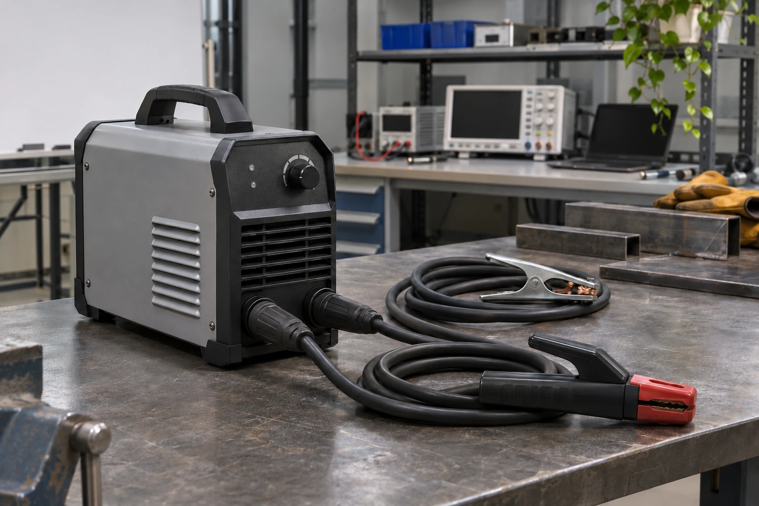
Illustrative welder development setting.
Locate the Commutation Event Before Choosing a Diode
An inverter welder contains several rectifying functions. The input bridge, a secondary output rectifier and a diode associated with a switching leg do not experience the same waveform. Locate the candidate on the schematic and identify which device forces it from forward conduction into blocking. An output-current label alone cannot describe that event.
For a secondary rectifier, transformer leakage, the output inductor and the commutation loop all influence current transfer. A switching frequency states how often a cycle repeats; it does not specify the slope or severity of an individual transition. Start the evaluation with the actual diode current and reverse voltage rather than the welder’s nameplate output.
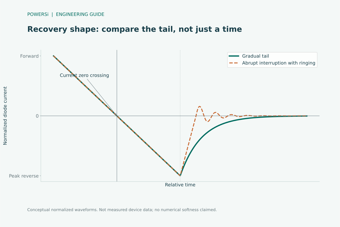
Conceptual waveform shapes; not measured POWERSi device data.
Read Softness as a Waveform Property
A commonly used softness definition is S = t_b / t_a: t_a runs from current zero crossing to peak reverse recovery current, and t_b describes the return toward the specified recovery endpoint. The endpoint and measurement conditions must match before numbers from different devices can be compared. Infineon’s Rapid diode selection guide illustrates this convention.
A more gradual recovery tail can reduce abrupt current interruption, but it is not an unconditional efficiency advantage. Examine peak reverse current and recovered charge as well. For the same total recovery time, different waveform shapes can impose different stresses on the commutating switch and stray inductance.
The conceptual waveforms below illustrate shape only. They are not test traces from a POWERSi device and do not establish a guaranteed softness factor.
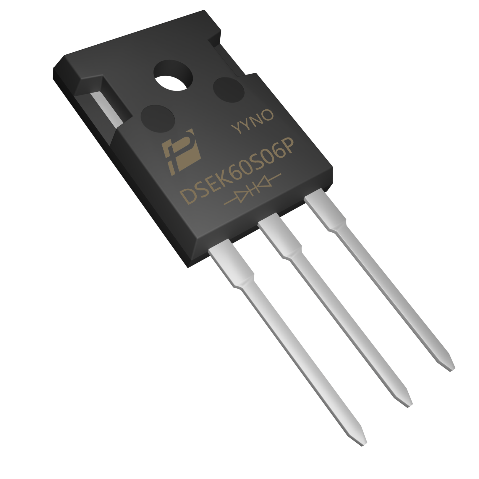
POWERSi DSEK60S06P product example.
Use a Real Candidate Without Assuming a Test Result
POWERSi DSEK60S06P is identified by POWERSi as an ultra-soft-recovery rectifier in a TO-247AD package. The product image identifies the three-lead device and its dual-diode construction. That identity is useful for a candidate discussion; it does not establish compatibility with a particular welding transformer or PCB.
Determine the current carried by each junction, its blocking-voltage requirement and its thermal path. A package-level current headline must not be assigned independently to both junctions without its stated conditions. If the project requires a numerical softness limit, obtain a recovery waveform or characterization at the intended forward current, reverse voltage, temperature and current slope. A descriptive family name cannot replace that evidence.
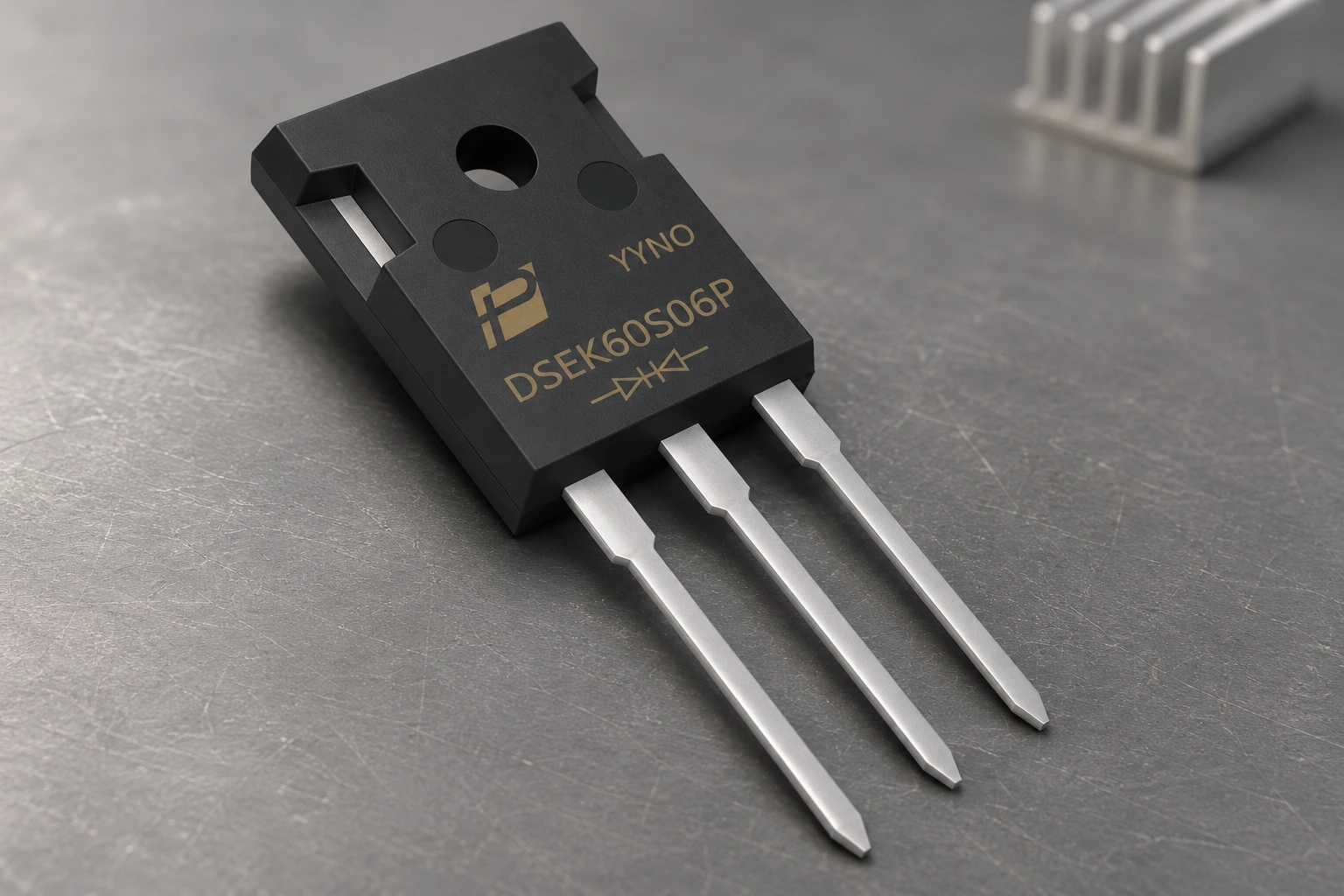
Product presentation; no electrical connection or test result is implied.
Build a Welder-Specific Test Matrix
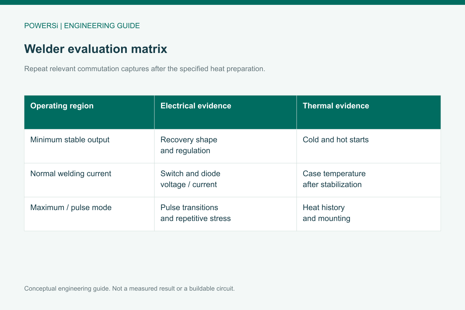
Use a matrix that includes minimum stable output, normal welding current and the maximum permitted output condition. At each relevant point, capture the rectifier’s commutation event after the specified thermal preparation. Include pulse welding modes and the transition into and out of a pulse when those modes are part of the design.
A cold, isolated double-pulse test is useful for controlled comparison, but it does not reproduce the welder’s complete thermal history. Use it to understand the switching mechanism, then validate the candidate in the actual repetitive waveform. Keep gate resistance, transformer connections, bus voltage and probe arrangement unchanged for the first A/B comparison.
Record the peak reverse voltage, recovery current, recovery tail, commutating-switch current and relevant case temperatures. Evaluate switching energy with voltage and current probes corrected for relative delay. An apparent reduction in energy can otherwise come from measurement timing rather than the new diode.
Conceptual engineering guide; no measured performance is shown.
Release the Pair of Devices and the Assembly
Define acceptance criteria before changing parts: device voltage and current limits, allowable switch and rectifier temperatures, stable regulation and the required emissions result. Do not accept a cleaner diode trace if the switch temperature increases beyond its margin.
If a softer candidate permits a later gate-drive or snubber optimization, treat that as a second design change and repeat the relevant measurements. Retain a record of the exact ordering code, board revision, mounting interface, drive setting and pulse program. Procurement can then compare a second source against a reproducible engineering requirement rather than the phrase “soft recovery.”
Key Takeaways
- Identify the diode position before interpreting welder output current.
- Compare recovery waveforms under matched electrical and thermal conditions.
- Approve switch stress and rectifier temperature as part of the same assembly.
Conclusion
A useful welder diode comparison reproduces the commutation event and the heat history that matter in service. Send POWERSi the circuit position, recovery captures, voltage envelope and mounting constraints to discuss a candidate for evaluation.
FAQs
Does a higher softness factor always mean lower loss?
No. Recovery charge, forward conduction and the commutating switch must be considered together.
Can rated welding current set the diode test current?
Not directly. Establish the current in the individual diode during the commutation event.
Is an isolated double-pulse test enough?
It characterizes a controlled event; repetitive operation and thermal history need additional validation.
Does DSEK60S06P have a guaranteed softness value here?
No numerical softness guarantee is stated in this article. The required evidence must match the project test conditions.
What belongs in a second-source release record?
Include the exact part, assembly revision, current waveform, drive settings, temperature preparation and acceptance results.