Skip to content

Reverse Polarity Protection: Schottky or PMOS?
Last Updated: 2026-11-16
Quick Answer
Reverse polarity protection can use a series Schottky diode or a correctly designed PMOS circuit. The diode is simple but dissipates forward power; the PMOS can reduce conduction loss while adding gate-drive and fault-state constraints. Compare voltage headroom, thermal cost and real fault behavior before choosing either approach.
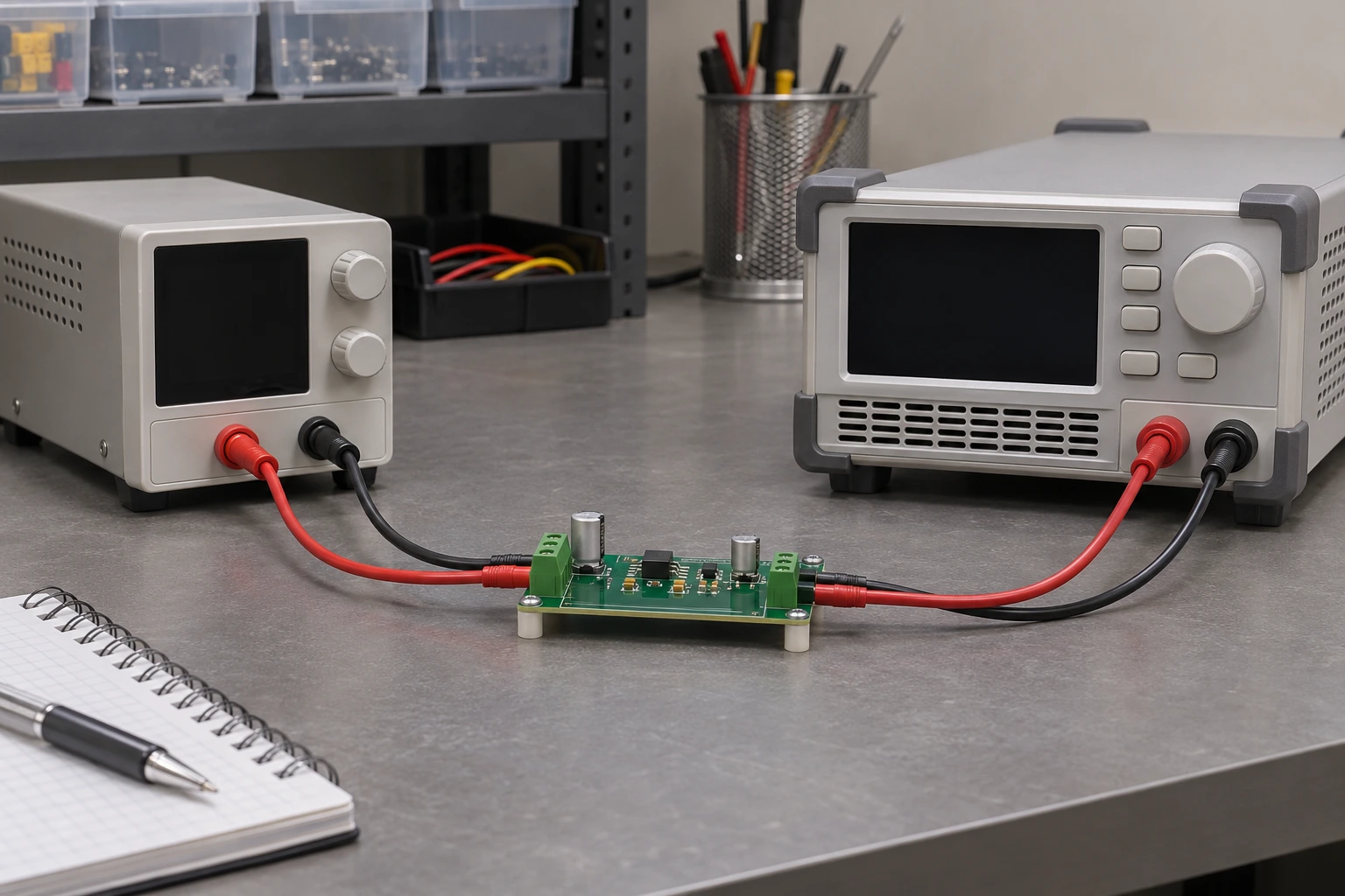
Illustrative low-voltage protection setup.
Write the Fault Requirement Before Drawing the Circuit
Reverse polarity means a source is connected with its terminals reversed. Reverse current means energy flows opposite to the intended direction, possibly with the input still correctly polarized. Bidirectional isolation is a third requirement. A solution to one does not automatically satisfy the others.
List every energized connection: main supply, battery, charger and externally powered interfaces. If a load-side source can remain active when the input disappears, include that state in the requirement. Start with the actual fault paths rather than the assumption that any circuit described as “reverse protection” covers them all.
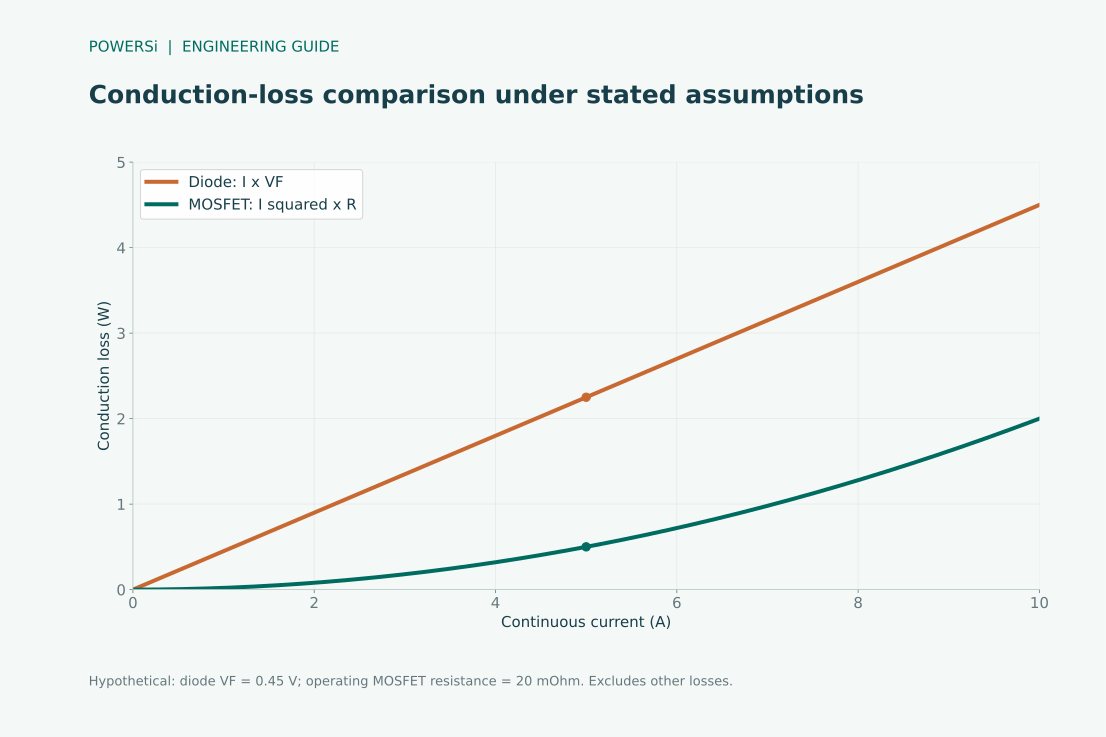
Hypothetical loss comparison using stated assumptions; not product measurements.
Compare Passive Forward Drop With Channel Resistance
A series diode blocks one direction and requires no gate circuit. During normal conduction, its approximate loss is current multiplied by forward voltage. In a conducting MOSFET channel, the resistive term is current squared multiplied by on-resistance at the relevant gate bias and temperature.
In a hypothetical constant-current example, 5 A through a diode at 0.45 V produces 2.25 W. A MOSFET at an actual operating resistance of 20 mΩ produces 0.50 W of channel loss at the same current. These are illustrative assumptions, not specifications for the photographed product. Add gate-network consumption and transient losses when comparing the complete implementation.
For a varying load, average the instantaneous losses. A room-temperature resistance measured at a stronger gate bias can overstate the PMOS advantage in a hot, low-voltage application.
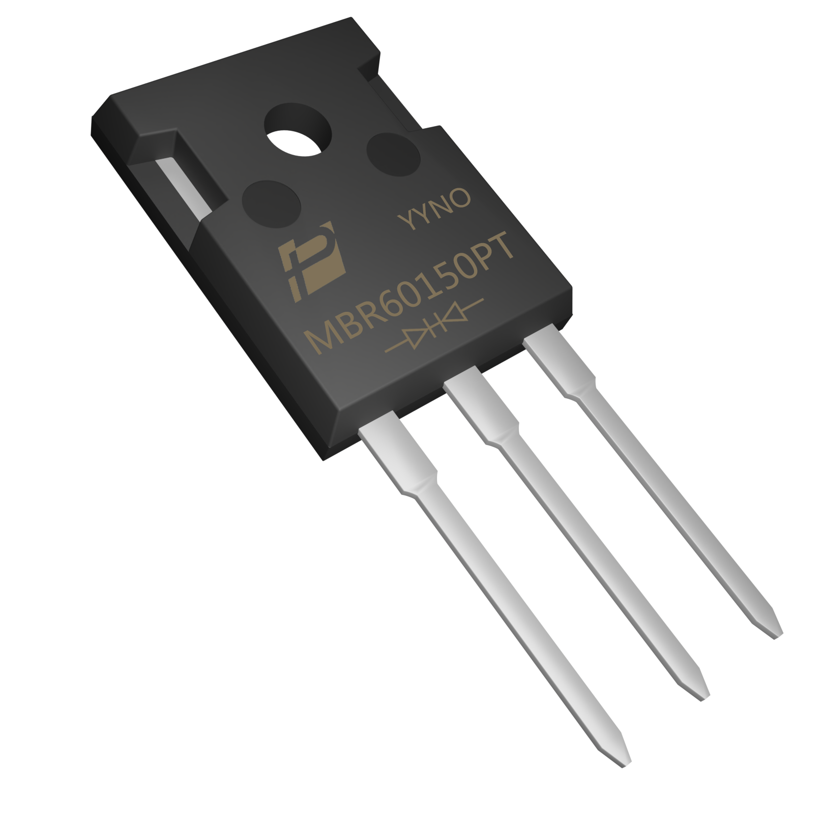
POWERSi MBR60150PT product example.
Check the Physical Candidate and the Thermal Budget
The POWERSi MBR60150PT product image shows a three-lead dual Schottky rectifier. Its package is useful where a through-hole thermal interface fits the assembly, but it is not automatically the smallest or most economical choice for a low-current input.
Resolve the dual-diode connection before using it in a series path. Do not assume the two junctions may simply share current equally because they occupy one package. Check the allowed reverse voltage, current distribution, forward loss, hot leakage and mechanical constraints for the intended connection.
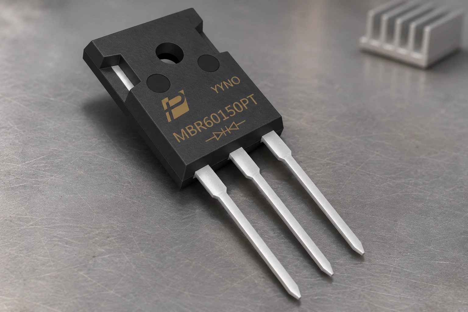
Product presentation; no fault-test result is implied.
Evaluate the PMOS Gate and Body-Diode States
A reverse-polarity PMOS circuit needs the correct device orientation and gate reference. Under normal polarity, startup may initially involve the body-diode path before the channel is enhanced. The gate-source voltage must remain within its limits through startup, input transients and reversed connection.
TI’s reverse battery protection application note describes the basic MOSFET approach and its conduction-loss benefit. A simple gate connection still needs examination when a charger or another source powers the output. With its channel on, a MOSFET can conduct in either direction; the usual one-FET reverse-polarity circuit is not a universal reverse-current blocker.
Test hot plugging, source removal and reconnecting the source while the output is charged. Include the gate clamp and its resistor in the loss and fault evaluation. Where controlled reverse-current blocking or bidirectional isolation is required, consider an appropriate controller or back-to-back switch architecture.
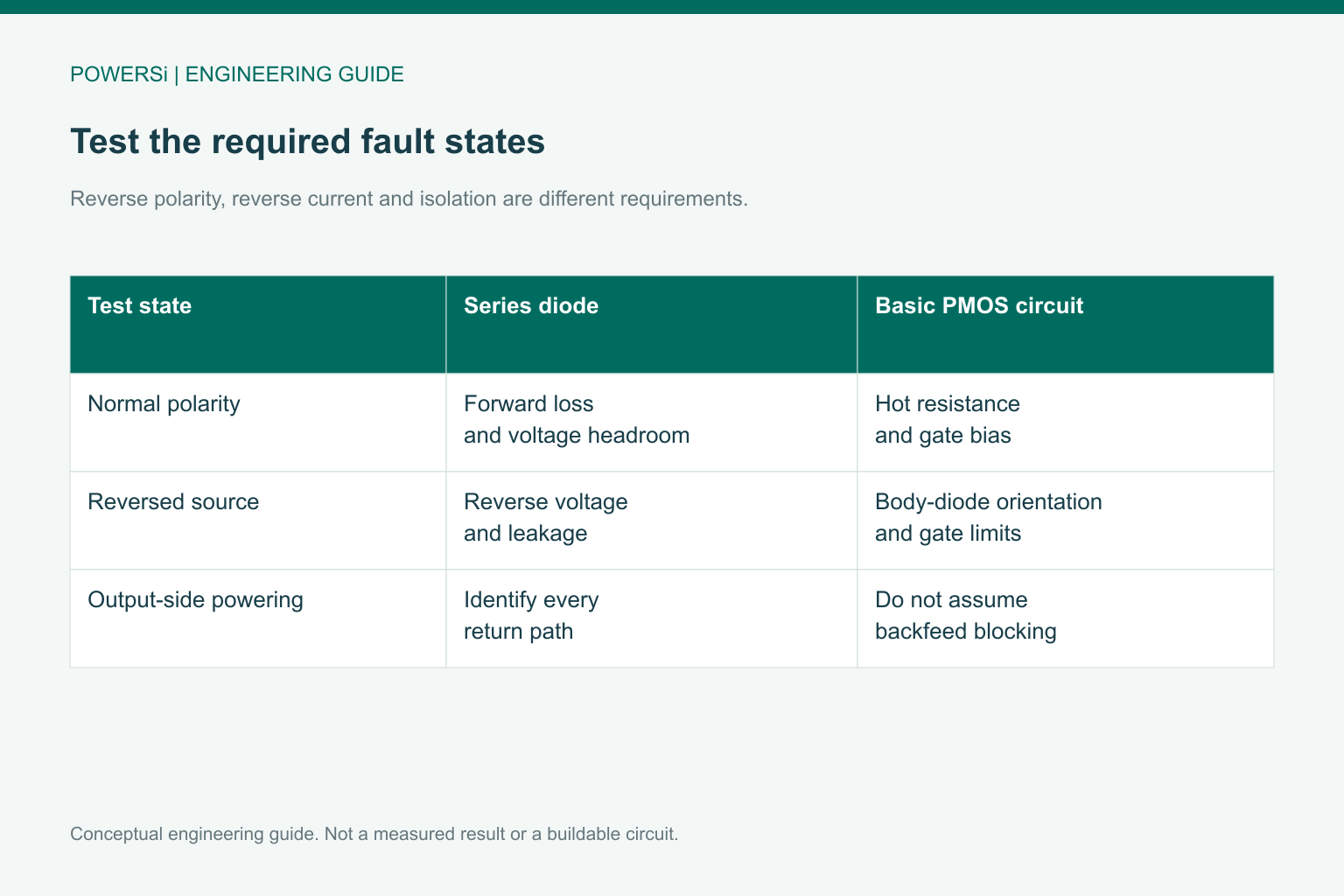
Conceptual engineering guide; no measured performance is shown.
Compare Installed Cost and Verifiable Fault Behavior
A diode often offers a short BOM and straightforward assembly. At higher current, its dissipated heat and voltage drop can require a larger package, more copper or a heatsink. The PMOS approach adds gate-network parts and validation work, but may save cooling area and preserve load voltage.
Run the same fault sequence on both candidates: correct input at load extremes, reversed input, minimum operating voltage, maximum specified transient and any load-side powering condition. Verify downstream voltage and component temperature. Record the expected failure response with the system protection strategy; neither technology can be called fail-safe merely from its normal-state schematic.
Select against the required function and total implementation cost. A cheaper diode may be appropriate for a low-current rail, while a MOSFET solution may justify its complexity where loss or voltage headroom dominates.
Key Takeaways
- Specify reverse polarity and reverse-current blocking separately.
- Compare losses using actual current, temperature and gate bias.
- Choose the total implementation that passes the required fault tests.
Conclusion
Choose the protection topology from the fault requirement, then compare its installed loss and cost. Contact POWERSi with the voltage range, load profile, reverse conditions and package constraints when evaluating a series Schottky option.
FAQs
Does reverse polarity protection also stop backfeed?
Only if the circuit is designed for that function. A basic one-MOSFET arrangement may not.
When is the Schottky approach attractive?
When simplicity, load current, voltage headroom and heat dissipation make its forward loss acceptable.
Can MOSFET loss be calculated from threshold voltage?
No. Use on-resistance at the actual gate bias and operating temperature.
Why test with a charged output?
Stored energy or another output-side source can create a current path absent from a cold-start test.
Is the lowest component price the lowest installed cost?
Not necessarily. Include cooling, board space, added parts and validation effort.