Skip to content

Drive Rectifier Thermal Simulation: Model the Shared Sink
Last Updated: 2026-11-10
Quick Answer
Drive rectifier thermal simulation should include the shared heatsink, nearby power losses, interface resistance and actual airflow. A bridge-only temperature estimate can miss heating from the inverter stage. Build the thermal model around the installed assembly, validate accessible temperatures experimentally, and evaluate overload and cooling degradation separately.
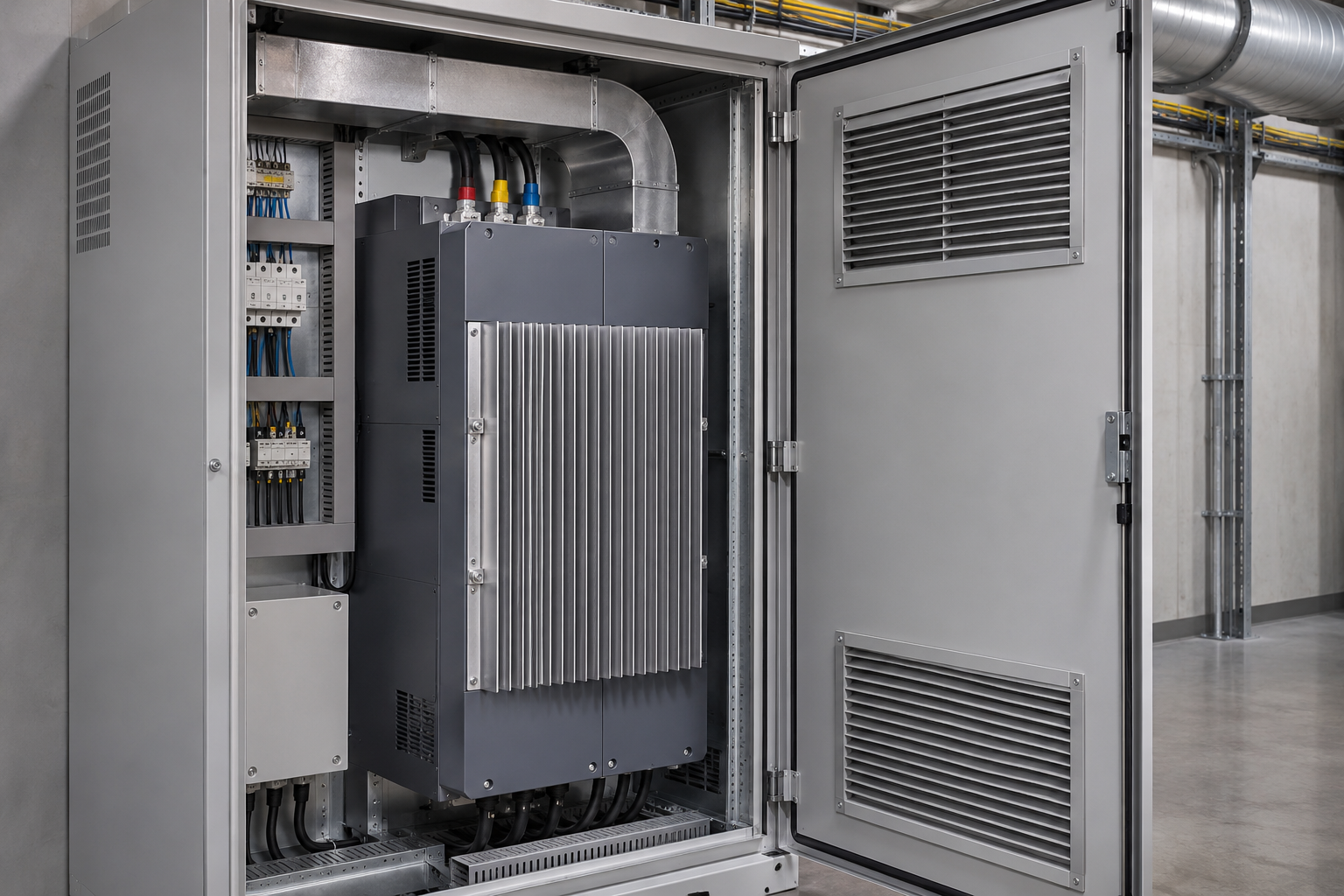
Define the Assembly Boundary
A motor drive may place its input rectifier and inverter switches on the same heatsink or in the same airflow path. Heat generated elsewhere can raise the bridge mounting temperature even when bridge dissipation is unchanged. Ambient room temperature is therefore not always the correct cooling reference.
Start with the actual input architecture. A three-phase drive front end is not equivalent to a single-phase bridge, and an active front end requires a different loss model. Identify the conducting devices and current waveform before assigning heat sources in the simulation.
Use the Correct Physical Reference
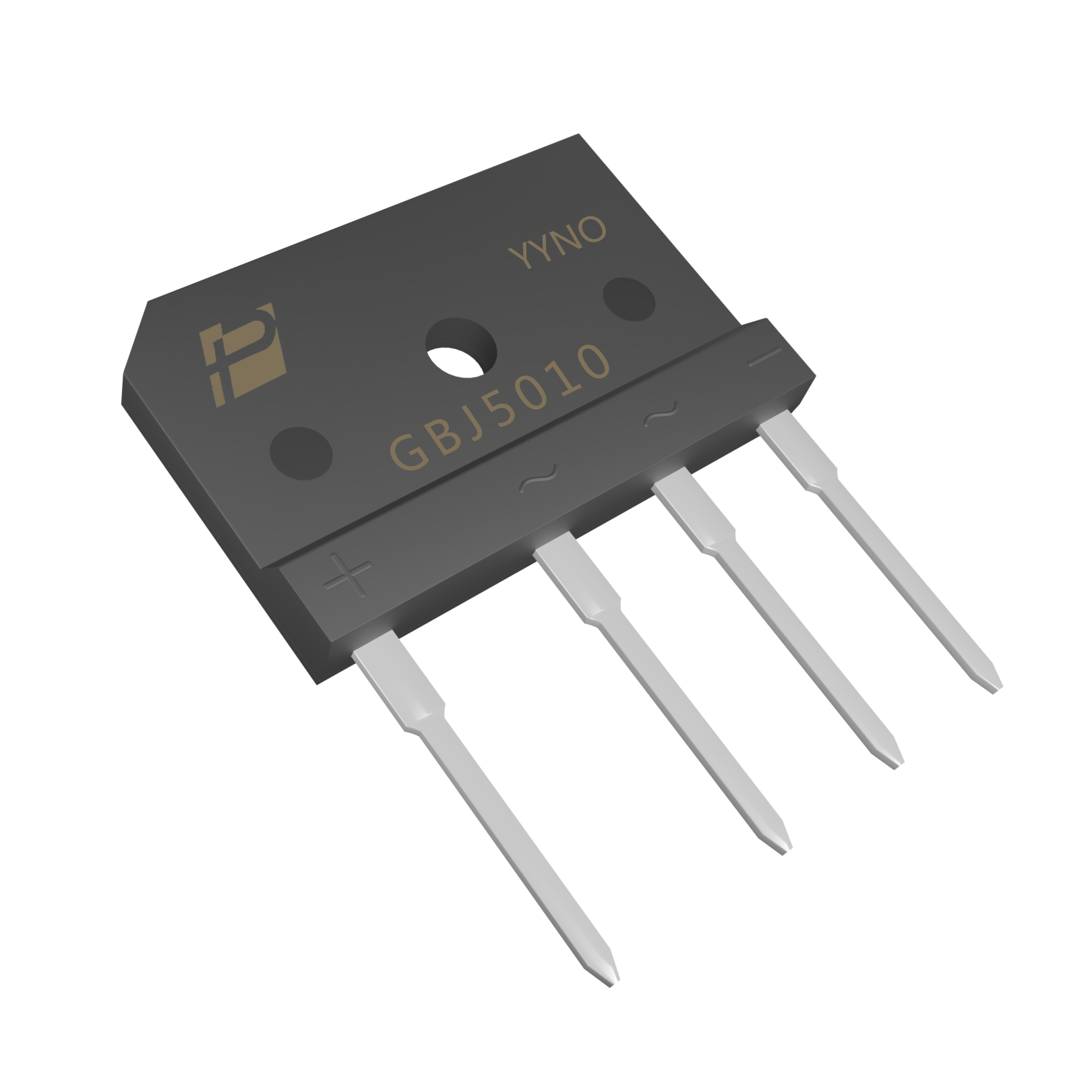
The GBJ5010 is shown as a four-lead, single-phase bridge-package example. It must not be interpreted as a complete three-phase rectifier recommendation for a high-power drive.
For the selected production part, obtain the mounting dimensions, allowable assembly conditions and applicable thermal data. Model the actual contact interface. A rendering of a mounting hole cannot establish bolt torque, electrical isolation or the thermal resistance of a pad.
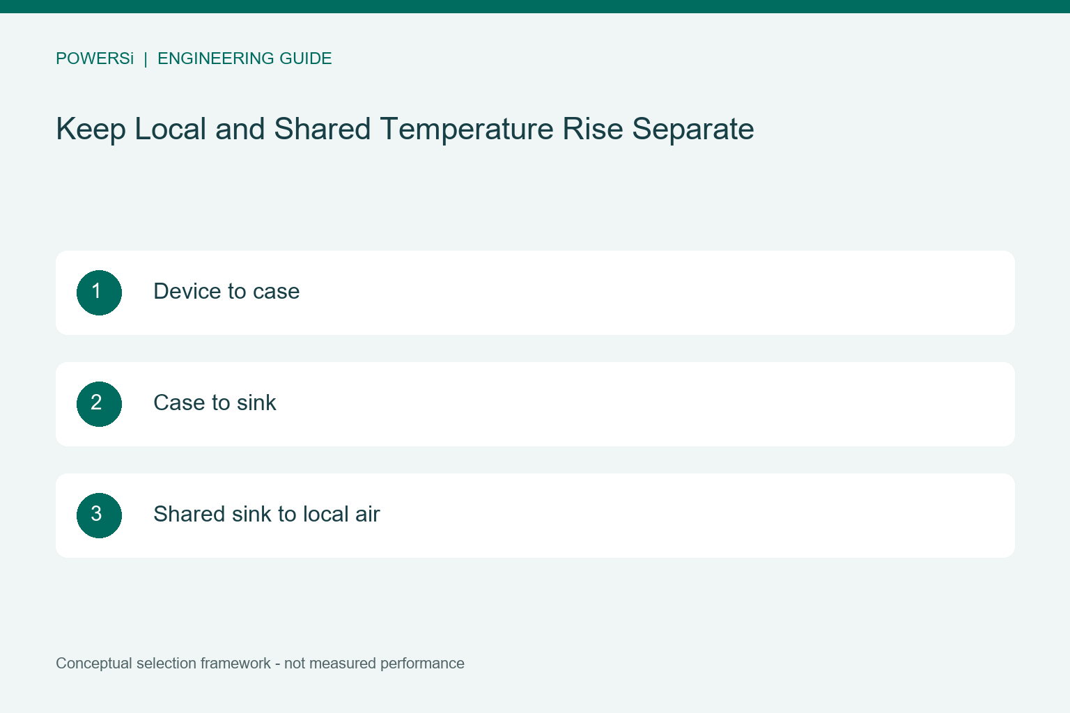
Keep Local and Shared Temperature Rise Separate
For a simple steady-state approximation, junction temperature equals local sink temperature plus the temperature rise through the device and interface paths. The sink temperature itself depends on all relevant heat sources and cooling boundaries. Do not add a full junction-to-ambient path to a separately modeled sink path; that double-counts part of the thermal network.
Multi-junction bridges require care with the definition of the published thermal resistance. Determine whether it applies per junction or to a specified operating condition. Distribute heat consistently with that definition rather than multiplying a headline bridge loss by an unrelated per-diode resistance.
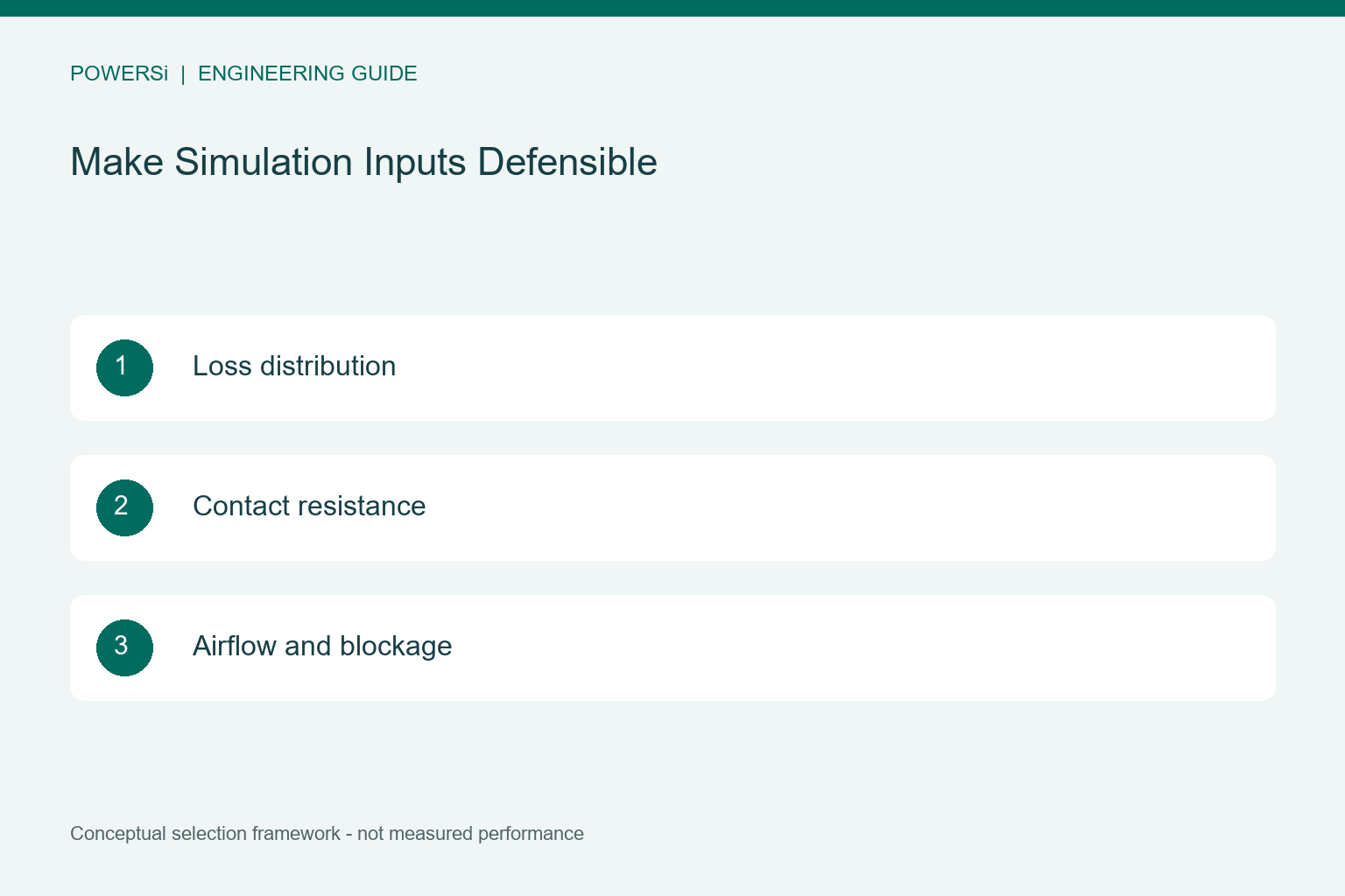
Make Simulation Inputs Defensible
Use geometry and materials representative of the assembly, including the interface layer and nearby airflow obstructions. Refine the mesh near heat sources and interfaces, then confirm that further refinement does not materially change the decision-driving temperatures.
Run sensitivity cases for interface resistance, fan performance, inlet temperature and neighboring device losses. A colorful temperature plot is not evidence of accuracy if these inputs are assumed optimistically. Keep assumed values visible in the engineering model, with a plan for measuring the influential ones.
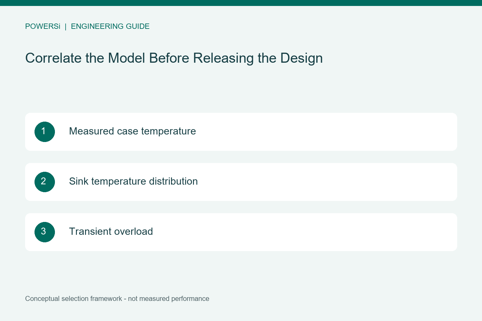
Correlate the Model Before Releasing the Design
Measure the bridge case and several heatsink locations under controlled load and airflow. Correct the measurement method for surface emissivity and sensor attachment effects. Accessible surface temperatures do not directly measure junction temperature; use a justified thermal model or an appropriate electrical temperature-sensitive parameter when necessary.
Investigate mismatches before adjusting a single coefficient merely to match one point. Validate another load or airflow condition independently. Evaluate short overloads using transient thermal behavior and the actual power history, not only steady-state resistance. For broader bridge context, see Vishay’s bridge rectifier documentation.
Key Takeaways
- Define the Assembly Boundary.
- Keep Local and Shared Temperature Rise Separate.
- Correlate the Model Before Releasing the Design.
Conclusion
Choose the rectification approach from the measured operating conditions and the complete system requirements. Contact POWERSi with your circuit role, voltage and current waveforms, thermal limits and package constraints to discuss a suitable component candidate.
FAQs
Can the bridge be simulated alone?
Only if the boundary conditions correctly represent heating and cooling from the rest of the assembly.
Is a four-lead bridge a three-phase bridge?
No. The input rectifier topology must match the drive.
Can case temperature be called junction temperature?
No. Their difference depends on loss and the thermal path.
Why perform a sensitivity study?
It identifies whether uncertain interface or cooling inputs can change the design decision.
Does a steady-state result cover overload?
No. Time-dependent loss and transient thermal response need separate evaluation.