Skip to content

LLC Output Rectifiers: Select Across the Operating Range
Last Updated: 2026-11-10
Quick Answer
LLC output rectifiers must tolerate the actual secondary current and blocking-voltage waveforms across the converter’s operating range. Resonant operation does not make every rectifier suitable. Evaluate conduction loss, commutation, capacitance and thermal behavior, and consider synchronous rectification when its efficiency benefit justifies the additional control requirements.

Why Resonance Does Not Settle Rectifier Selection
The LLC tank shapes current, but the rectifier sees the result of the transformer, resonant network, output arrangement and operating point together. A favorable nominal-load waveform does not guarantee equally gentle behavior during startup, overload or operation far from the nominal frequency.
A general-purpose line-frequency rectifier should not be selected merely because its voltage and current ratings look adequate. Recovery behavior and capacitive interaction with the circuit can matter. Conversely, there is no useful blanket rule that every passive diode is unsuitable for LLC output service.
Separate Package Compatibility From Electrical Choice
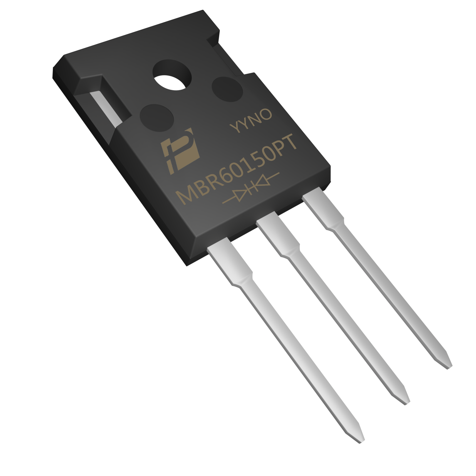
The MBR60150PT original image shows the exact POWERSi product used as a package example. It is not an LLC reference-design approval.
Before choosing a model, establish whether the secondary is center-tapped or uses another rectification arrangement. Determine the reverse stress on each device and the current carried by each junction. Output voltage alone does not equal the maximum diode reverse voltage; transformer action and ringing must be included.
Calculate the Loss That the Secondary Actually Produces
Use the measured or validated simulated rectifier current to calculate average forward loss. Evaluate reverse behavior at the voltage and temperature reached in service. Include layout and transformer parasitics when investigating oscillation; changing the diode cannot compensate for every source of ringing.
Inspect the waveforms with suitable probes and controlled loop area. Comparing traces taken with different probe grounding can lead to a false conclusion about the replacement. A convincing improvement should appear in repeatable waveforms and in the complete converter’s loss and temperature measurements.
Consider Synchronous Rectification as a System Change
Synchronous rectification can reduce conduction loss on low-voltage, high-current outputs, but it adds a controller and timing constraints. TI’s UCC24624 evaluation module is intended to investigate conversion from diode to synchronous rectification in an LLC stage.
Treat that conversion as a controlled design change. Check sensing accuracy, turn-off behavior, light-load operation and startup. A MOSFET selected only for low room-temperature resistance may have unfavorable charge or drive requirements. The rectifier, controller and board layout need evaluation as a combination.
Build a Release Matrix
Record the diode or MOSFET voltage peak, current peak, case temperature and output regulation for each limiting condition. Include load steps and the transitions into burst or standby behavior when implemented. Repeat relevant tests after thermal soak.
Keep the approved BOM and layout revision with the test results. If a second source changes capacitance or commutation behavior, repeat the affected measurements rather than assuming that matching nominal voltage and current establishes equivalence.
Key Takeaways
- Why Resonance Does Not Settle Rectifier Selection.
- Calculate the Loss That the Secondary Actually Produces.
- Build a Release Matrix.
Conclusion
Choose the rectification approach from the measured operating conditions and the complete system requirements. Contact POWERSi with your circuit role, voltage and current waveforms, thermal limits and package constraints to discuss a suitable component candidate.
FAQs
Can LLC converters use diode rectification?
Yes, if the devices meet the loss and stress requirements across the operating range.
Is output voltage sufficient to set reverse rating?
No. The secondary arrangement and transient waveform determine reverse stress.
Why test away from resonance?
The current and commutation conditions may change as the controller regulates the output.
Is synchronous rectification a drop-in diode change?
Usually it requires controller, layout and timing evaluation.
What evidence supports a second source?
Matched operating-envelope tests, thermal results and controlled configuration records.