 Skip to content
OBC Rectifier Selection: Reliability Starts With Circuit Role
Last Updated: 2026-10-13
Quick Answer
OBC rectifier selection starts with the charger’s topology, power direction and device location. Passive boost diodes, active rectifiers and auxiliary diodes have different duties. Match electrical and thermal requirements to the exact component, then connect automotive qualification evidence, mission-profile assessment and production traceability to the ordering code actually supplied.
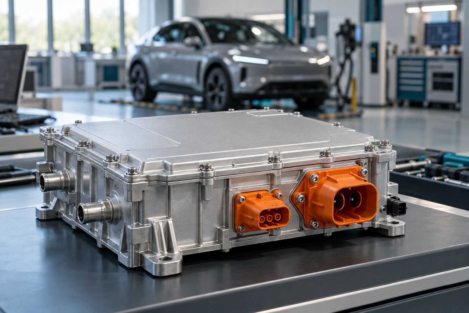
Illustrative application scene; not a customer installation or a measurement result.
Locate the Rectifying Function in the OBC
The word rectifier does not identify one universal component inside an onboard charger. A conventional boost PFC stage may use a discrete boost diode; an active architecture can assign that function to controlled switches. Auxiliary supplies and protection paths can still contain diodes with very different voltage and current requirements.
TI’s PMP22650 onboard charger reference design uses totem-pole PFC and a CLLLC converter with synchronous rectification. It is a useful example of why a bidirectional OBC should not be reduced to selecting one large passive output diode. Establish the schematic location before comparing suppliers or technologies.
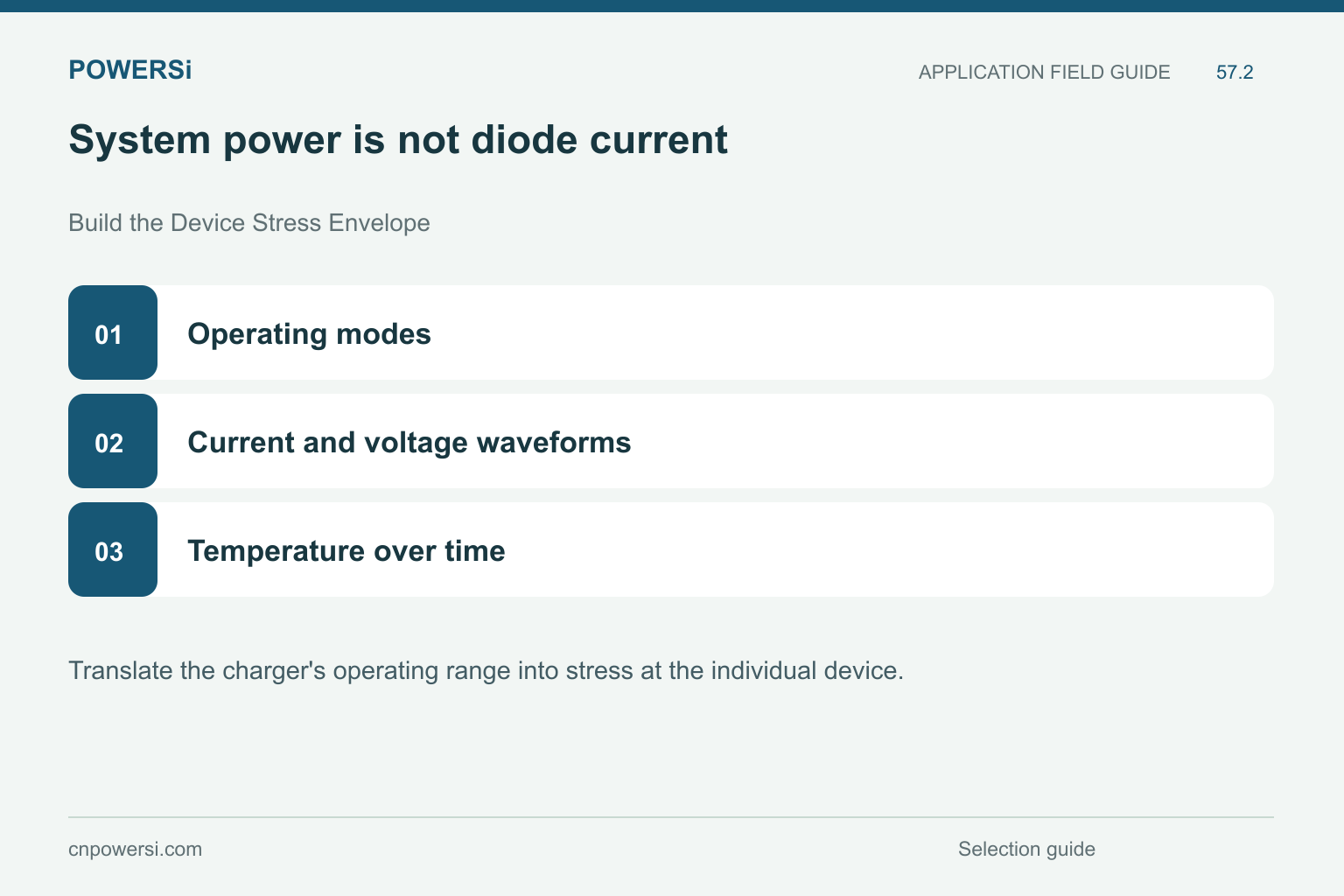
System power is not diode current.
Build the Device Stress Envelope
Translate the charger’s operating range into stress at the individual device. Identify repetitive blocking voltage, overshoot, conduction intervals, pulse current and commutation conditions. A vehicle’s battery voltage or charger nameplate power does not directly define every diode’s required rating.
| Operating condition | Evidence to collect |
|---|---|
| Normal charging | Device current, reverse stress and losses across line and load |
| Reverse power flow, if supported | The active current path and changed commutation conditions |
| Startup and shutdown | Precharge, sequencing and abnormal pulse exposure |
| Thermal extremes | Cooling conditions, hot restart and temperature cycling |
Include control transitions and the events identified by the system requirements. Do not extrapolate from one rated-load waveform to every operating mode.
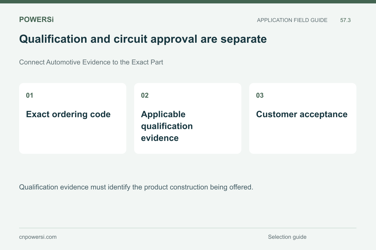
Qualification and circuit approval are separate.
Connect Automotive Evidence to the Exact Part
Qualification evidence must identify the product construction being offered. AEC-Q101 addresses qualification of discrete semiconductors; it does not approve every circuit that uses a qualified part. Renesas describes the scope of AEC-Q101, including new-product and major-change qualification requirements.
Request the applicable report or qualification summary, its revision and the relationship between the tested construction and the supplied ordering code. Keep manufacturing-site and change information traceable. A catalogue claim, high junction-temperature rating or another product’s qualification cannot substitute for evidence covering the candidate.
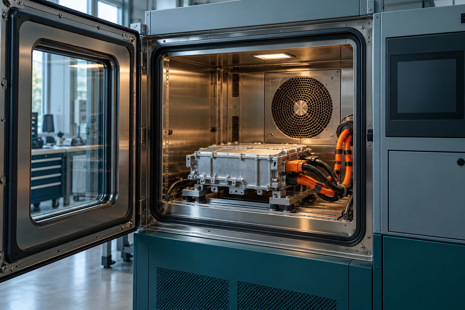
Illustrative application scene; not a customer installation or a measurement result.
Evaluate Reliability in the Installed Assembly
A reliable OBC assembly depends on more than the semiconductor junction. Evaluate package mounting, electrical isolation, solder or terminal connections and the installed cooling interface. Include the application’s temperature excursions and operating durations when assessing the component’s workload.
Environmental and endurance tests need a defined purpose and acceptance criteria. An environmental chamber photograph is not qualification evidence, and a room-temperature demonstration is not a lifetime prediction. Link each required test to the relevant failure concern, retain sample identification and examine whether the assembled unit represents the intended production materials and process.
Release the evaluated configuration.
Manage a Second Source Through Production Release
A replacement project should record both the original requirements and the candidate’s differences. Compare the relevant dynamic behavior, leakage, surge limits and cooling needs under matching conditions. Where the topology uses active rectification, do not force a passive diode into a role that requires controlled bidirectional operation.
Provide POWERSi with the exact component function and automotive evidence requirements before discussing candidates. After evaluation, connect approval to the ordering code, assembly configuration and traceable lots. Agree how future changes will be communicated and assessed. This keeps a sourcing decision tied to the actual OBC requirements rather than a generic automotive label.
Key Takeaways
- Map the charger before choosing a diode.
- Qualification and circuit approval are separate.
- Release the evaluated configuration.
Conclusion
Start with the circuit role and required qualification scope. Share those requirements with POWERSi before choosing a rectifier candidate for an OBC evaluation.
FAQs
Does every OBC need a passive output rectifier?
No. Some architectures use synchronous rectification and controlled bidirectional stages.
Does AEC-Q101 evidence approve the whole charger?
No. Component qualification and application acceptance are separate.
Can an industrial diode be called automotive because it tolerates high temperature?
No. Temperature capability does not establish an automotive qualification claim.
Why include startup in selection?
Startup and sequencing can produce current and voltage stresses absent from steady operation.
What should purchasing release?
The exact evaluated ordering code and assembly configuration with traceable supporting evidence.


