 Skip to content
PV Bypass and Blocking Diodes: Where Low VF Matters
Last Updated: 2026-10-13
Quick Answer
PV bypass and blocking diodes solve different problems. A low forward drop reduces heat while a diode conducts, but reverse leakage, blocking voltage and the installed thermal path also determine suitability. Choose the circuit function first; neither a solar application nor a Schottky label establishes a universal replacement rule.
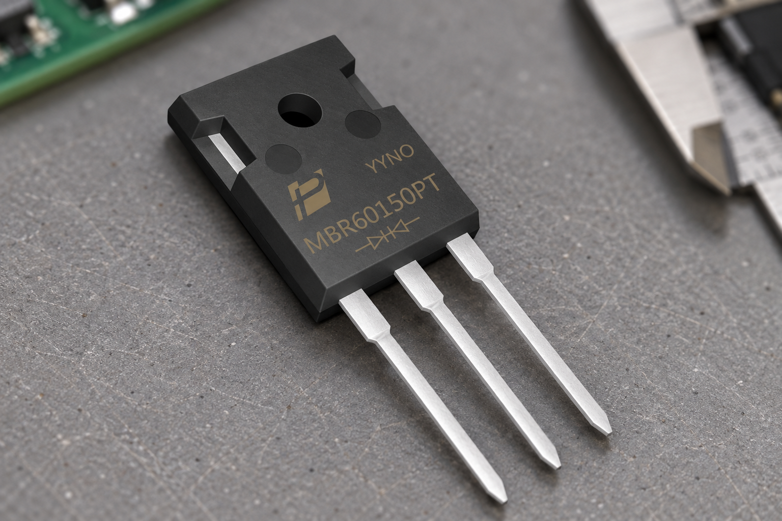
Product scene based on the supplied MBR60150PT reference; application suitability is evaluated separately.
Separate the Two Current Paths
A bypass diode provides an alternative current path around a shaded or weak cell group. A blocking diode sits in a series path to oppose unwanted reverse current. Their normal conduction states and reverse-voltage exposure are different, so they should not share an unexamined selection checklist.
These functions often belong to the PV module or its DC interconnection rather than the inverter’s high-frequency switching stage. Vishay’s PV module application overview distinguishes bypass and blocking functions. Start with a schematic showing the protected cell group, module, string or low-voltage branch. Identify every source that can drive reverse current, including parallel strings and batteries where present.
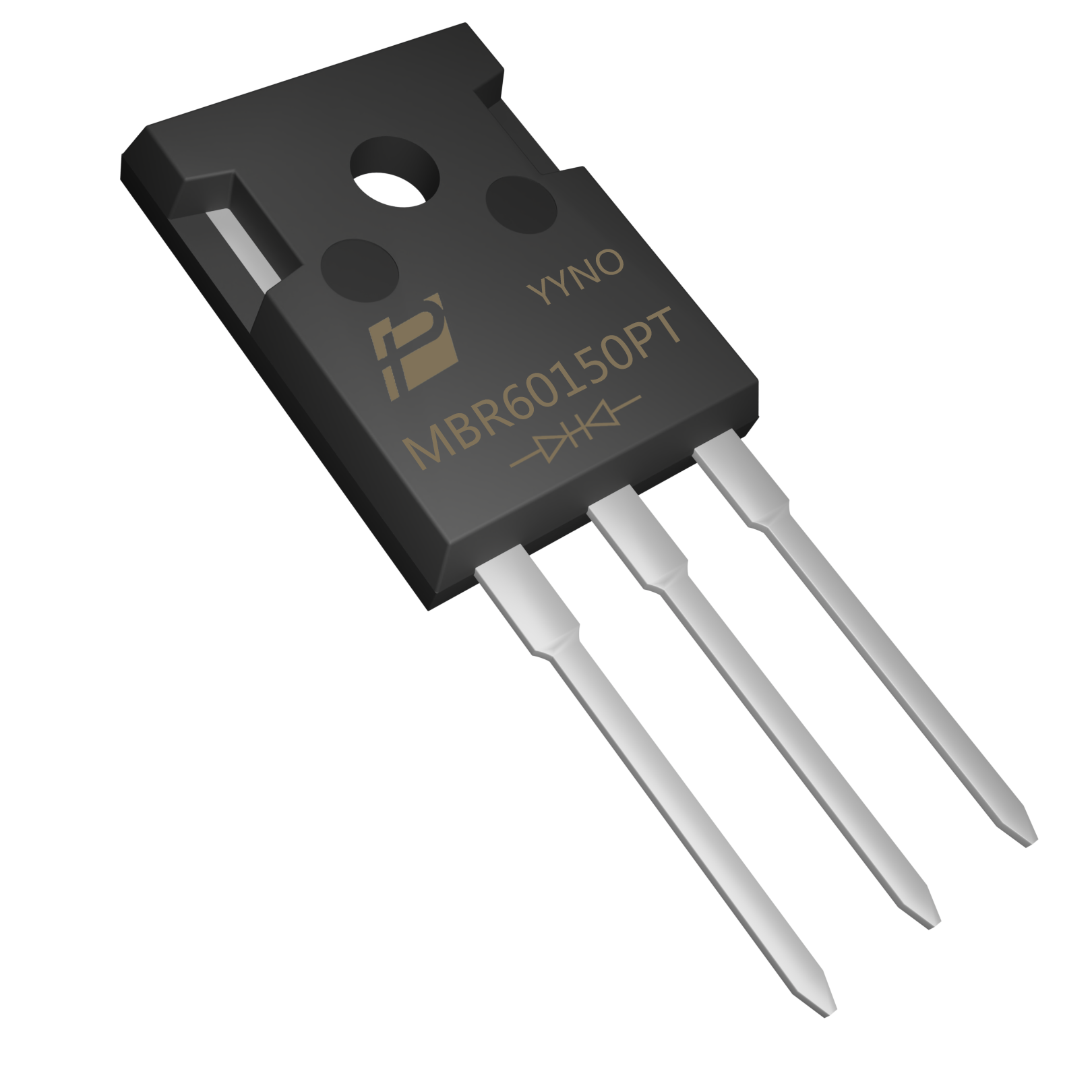
Supplied MBR60150PT product reference; no system-level suitability or qualification is implied.
Screen a Real Product Without Assuming Solar Approval
A documented device makes the selection discussion concrete. POWERSi MBR60150PT is a 150 V Schottky rectifier in a three-lead TO-247AD package, with a dual common-cathode connection in the supplied V2 documentation. The original product image identifies that construction; it does not establish approval for a particular PV junction box.
A 150 V device must not be assigned to block a high-voltage string whose stress exceeds its rating. Even in a suitable lower-voltage branch, check how each internal diode connects and carries current. A dual device cannot be treated as two completely independent diodes because the common terminal constrains the available connections.
Compare both conducting and blocking states.
Balance Forward Drop Against Hot Leakage
Lower forward voltage is useful when the diode is carrying current. For approximately steady conduction, a first estimate is P = IF × VF. As a hypothetical illustration, reducing VF by 0.15 V at 10 A reduces conducting loss by 1.5 W.
Reverse leakage creates a separate loss term, approximately VR × IR under steady blocking. Compare leakage at the relevant voltage and temperature, not only at room temperature. Vishay’s solar bypass application note discusses the trade-off between low forward voltage and leakage at elevated temperature.
| State | Principal selection question |
|---|---|
| Bypass conduction | Can the installed diode carry the bypass current without overheating? |
| Normal blocking | Is leakage acceptable at the actual reverse voltage and temperature? |
| Transient event | Do the protection arrangement and device limits cover the event? |

Illustrative application scene; not a customer installation or a measurement result.
Evaluate the Junction Box or Branch Assembly
The installation determines how heat leaves the device. Include the enclosure, copper connections, potting materials where used and local heating from adjacent parts. A current rating obtained at a controlled case or lead temperature cannot be treated as an ambient-temperature guarantee.
Assess sustained shading as well as transitions into and out of bypass. Check connection resistance and mechanical stress over the intended environmental exposure. Use the relevant module or system qualification process; a successful open-bench test does not establish long-term suitability inside a sealed assembly. Do not infer a thermal-runaway threshold from the diode technology name alone.
Low VF is one decision input.
Choose the Protection Architecture Before the Part
A passive diode is one way to implement blocking, but some systems use controlled MOSFET arrangements to reduce conduction loss or manage reverse current. The controller’s operating limits and behavior during loss of power then become part of the decision. TI’s reverse-current protection discussion illustrates the distinction between a diode and controlled switching approaches.
For a POWERSi inquiry, provide the protected circuit segment, maximum reverse voltage, current waveform and thermal arrangement. Request a specific ordering option and assess it in that installation. Low VF can help the loss budget, but it cannot compensate for insufficient voltage capability, excessive hot leakage or the wrong internal connection.
Key Takeaways
- Bypass and blocking are different jobs.
- Compare both conducting and blocking states.
- Low VF is one decision input.
Conclusion
Define bypass and blocking requirements separately, then compare losses in both operating states. Contact POWERSi with the complete circuit and installation requirements for a model-specific discussion.
FAQs
Are bypass and blocking diodes interchangeable functions?
No. Bypass provides a parallel path around a cell group; blocking opposes reverse current in a series path.
Must every PV diode be a low-VF Schottky?
No. The function, voltage, leakage, thermal path and architecture determine the appropriate solution.
Is MBR60150PT approved here for any PV module?
No. It is a documented product example requiring application-specific assessment.
Does lower VF always mean lower total loss?
No. Blocking leakage and the time spent in each operating state also matter.
What should a supplier receive first?
The protected circuit segment, voltage exposure, current waveform and installed thermal conditions.


