 Skip to content
EV Charger Module Rectifier Alternatives: From Circuit Role to Release
Last Updated: 2026-10-08
Quick Answer
EV charger module rectifier alternatives must be matched to the converter stage, operating direction and system requirements. Input rectification, PFC and isolated DC-DC conversion can impose different conduction and switching duties. Evaluate the exact candidate in its circuit, including startup, protection, thermal interaction and production consistency, before approving a sourcing change.
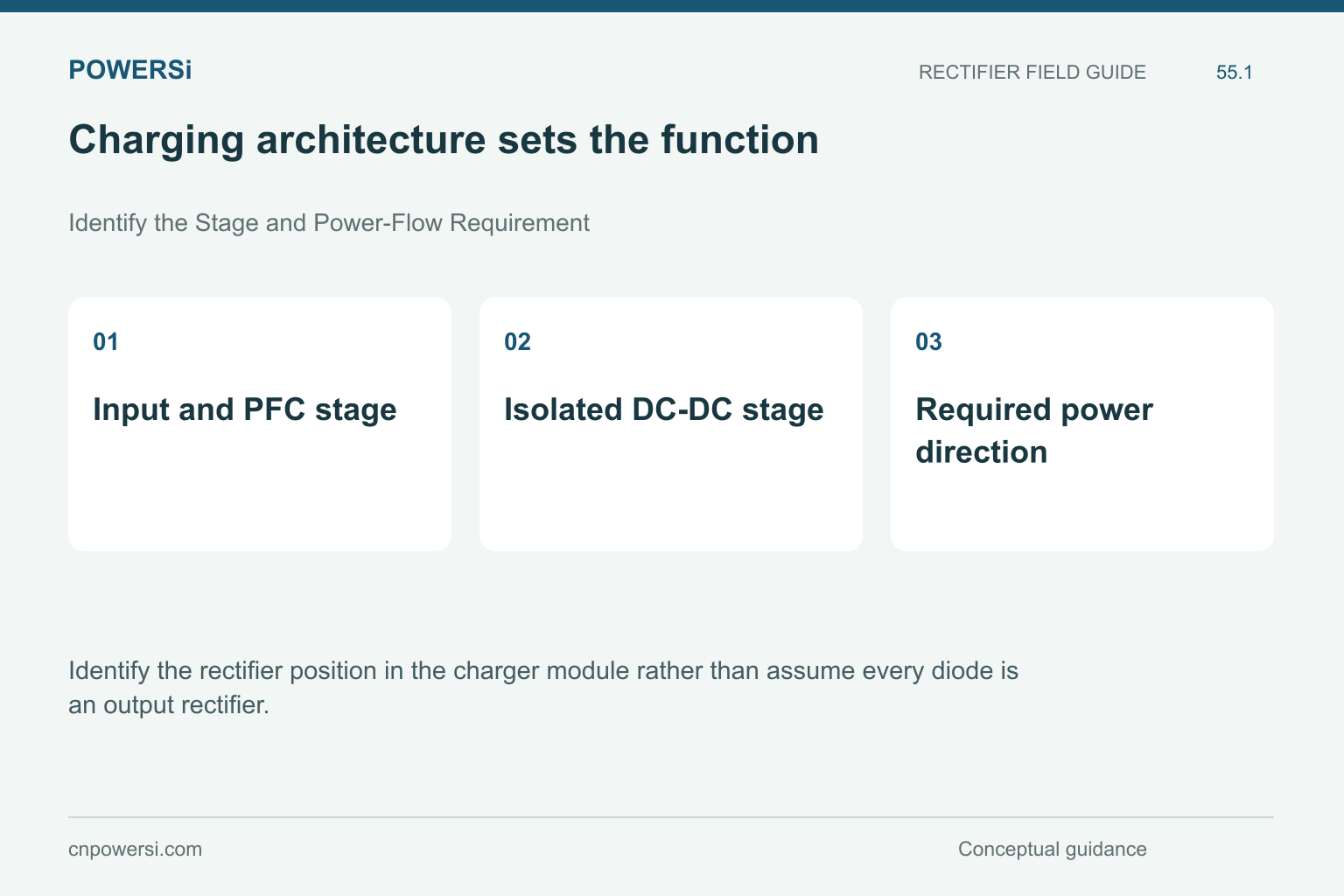
Charging architecture sets the function.
Identify the Stage and Power-Flow Requirement
Identify the rectifier position in the charger module rather than assume every diode is an output rectifier. ST’s EV charging overview describes grid-fed DC charging conversion using PFC and isolated DC-DC stages. Actual implementations vary.
Confirm whether the design requires unidirectional or bidirectional operation. A passive diode cannot independently provide a controlled reverse-power path. A candidate that matches a voltage class but changes the intended function is not a component-level substitute.
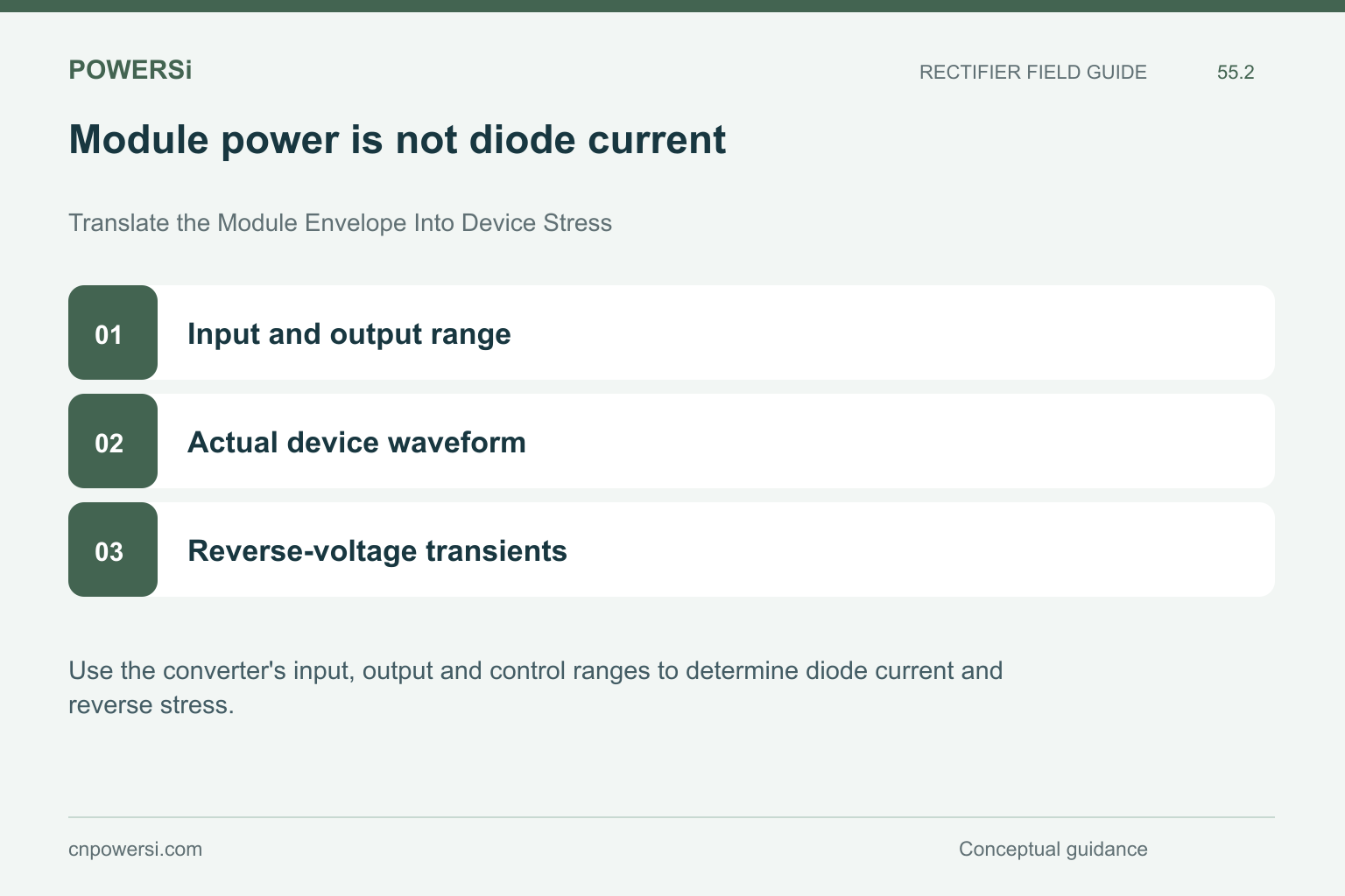
Module power is not diode current.
Translate the Module Envelope Into Device Stress
Use the converter’s input, output and control ranges to determine diode current and reverse stress. Module output power alone does not reveal current in every internal path. Include the relevant conduction interval and transient behavior.
For a charger covering a broad output range, identify the operating points that maximize current, loss or blocking stress; they may not coincide. Preserve the calculation or measurement basis when comparing candidates so purchasing does not reduce the requirement to one current and voltage pair.
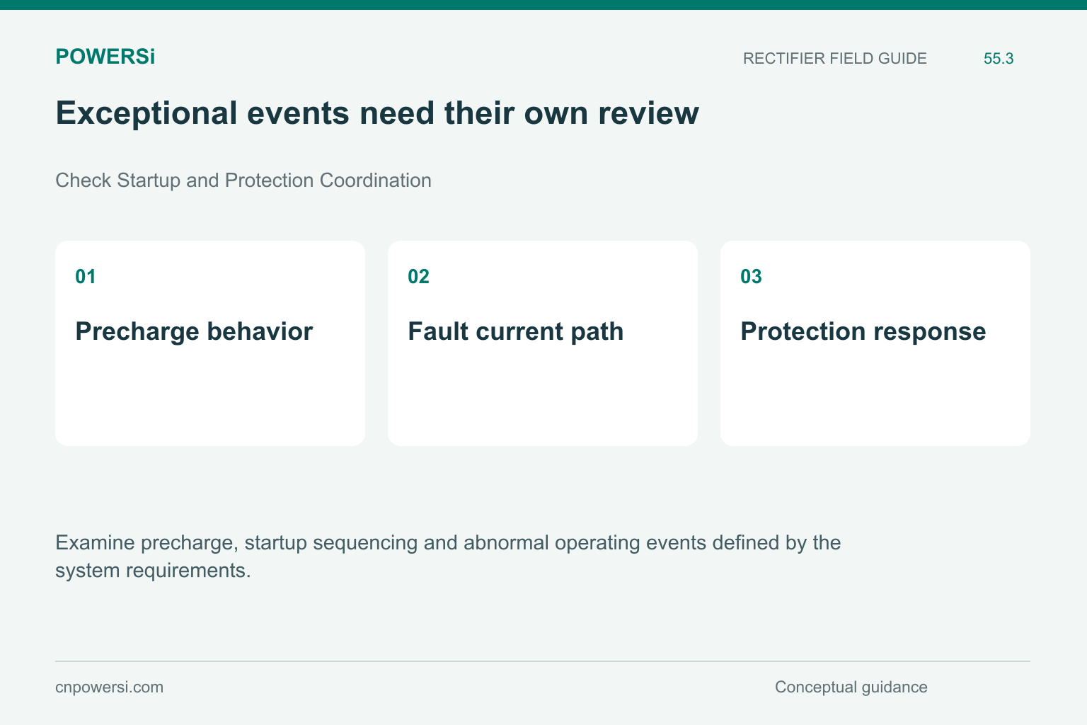
Exceptional events need their own review.
Check Startup and Protection Coordination
Examine precharge, startup sequencing and abnormal operating events defined by the system requirements. Determine which device carries inrush or fault current and how long the protection system allows it to flow. Do not assume the PFC boost diode should absorb all bulk-capacitor charging stress.
Compare the relevant surge conditions, initial temperature and repetition. If the candidate requires a changed protection strategy, include that system change in the project scope. A successful steady-state efficiency test does not close startup or fault-survival questions.

Neighboring losses affect the result.
Evaluate Heat in the Complete Module
Evaluate the device in the actual cooling arrangement, including interface materials and nearby heat sources. A cooler measured case can reflect a changed mounting contact rather than lower junction stress. Use a thermal model with clearly defined reference points and validate it appropriately.
Keep airflow or coolant conditions consistent during comparisons. In parallel module systems, distinguish module-level loading from individual device sharing. Do not infer equal thermal performance from equal package names or assume one successful module establishes the behavior of every installation.

A sourcing change reaches beyond the lab.
Manage Release Across Repeated Production
Release the exact component and assembly configuration after the required application evidence is complete. Link pilot results to traceable production lots and establish how material changes will be communicated. Agree the incoming controls relevant to the identified risks.
A charger installation is not automatically an automotive-component qualification claim for every internal device. Apply the actual customer and system requirements. The opportunity for local sourcing is an evidence-backed alternate and dependable supply, not an unsupported promise of universal compatibility or guaranteed charging performance.
Key Takeaways
- Charging architecture sets the function.
- Exceptional events need their own review.
- A sourcing change reaches beyond the lab.
Conclusion
Define the circuit position and module envelope before requesting a local alternate. Contact POWERSi with the full electrical, thermal and qualification requirements.
FAQs
Can a passive diode provide bidirectional controlled power flow?
No. The architecture must provide the required controlled paths.
Does charger output current equal every internal diode current?
No. Topology and conduction intervals determine each device waveform.
Does steady-state testing cover precharge?
No. Startup and protection events require their own assessment.
Does a matching package prove equal cooling?
No. Device losses, interfaces and neighboring heat sources also matter.
Are all charger components automatically automotive qualified?
No. Verify the exact device claim and the applicable customer requirements.


