Skip to content

Last Updated: November 5, 2026
Key Engineering Takeaways
- Compare SiC and ultrafast silicon diodes within the same PFC operating envelope.
- Check per-path current, reverse-voltage stress, surge and thermal conditions before testing.
- Use measured system behavior and actual quotations in the cost comparison.
Quick answer: In a hard-switched continuous-conduction-mode (CCM) boost PFC, a SiC Schottky diode can reduce minority-carrier recovery effects relative to an ultrafast silicon PN diode. The purchase price alone cannot decide the winner: measure both designs’ switching energy, conduction loss, temperature and EMI, then include any cooling, component and qualification changes in the cost comparison.
Begin with the same circuit role
In a conventional boost PFC, the boost diode conducts inductor current into the DC bus when the switch turns off. When the switch turns on, a silicon PN diode must remove stored charge before it blocks. Its recovery current adds to the switch current at turn-on. A SiC Schottky diode does not have the same minority-carrier storage mechanism, but junction capacitance still has to charge and discharge; its switching energy is not automatically zero. This difference can matter particularly in hard-switched CCM, where the diode was conducting immediately before turn-on. For a discontinuous or other soft-commutation operating point, repeat the analysis: the benefit can be different. See Infineon’s boost PFC guide and its SiC diode selection guide.
Shortlist on blocking, current and cooling first
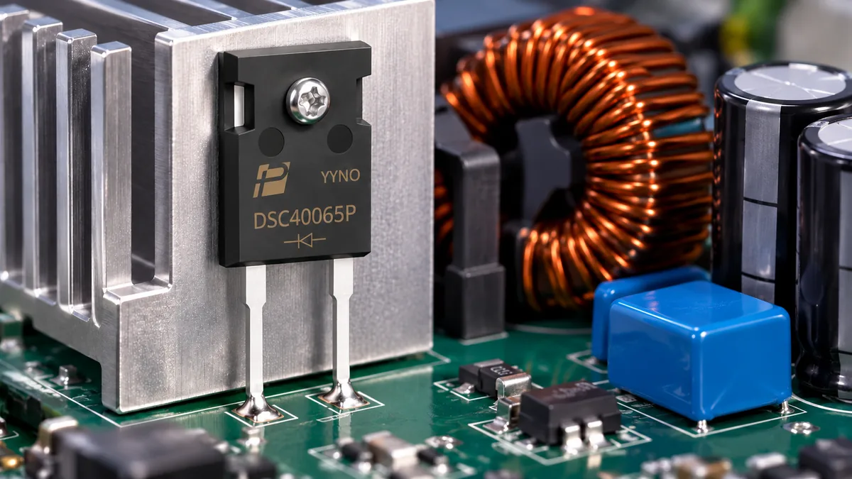
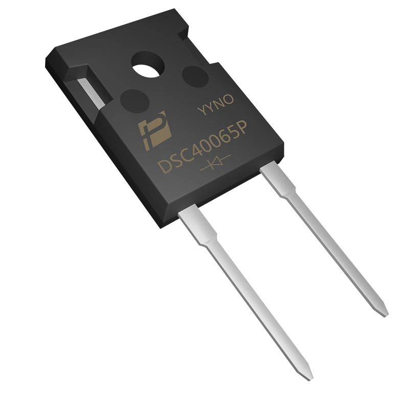
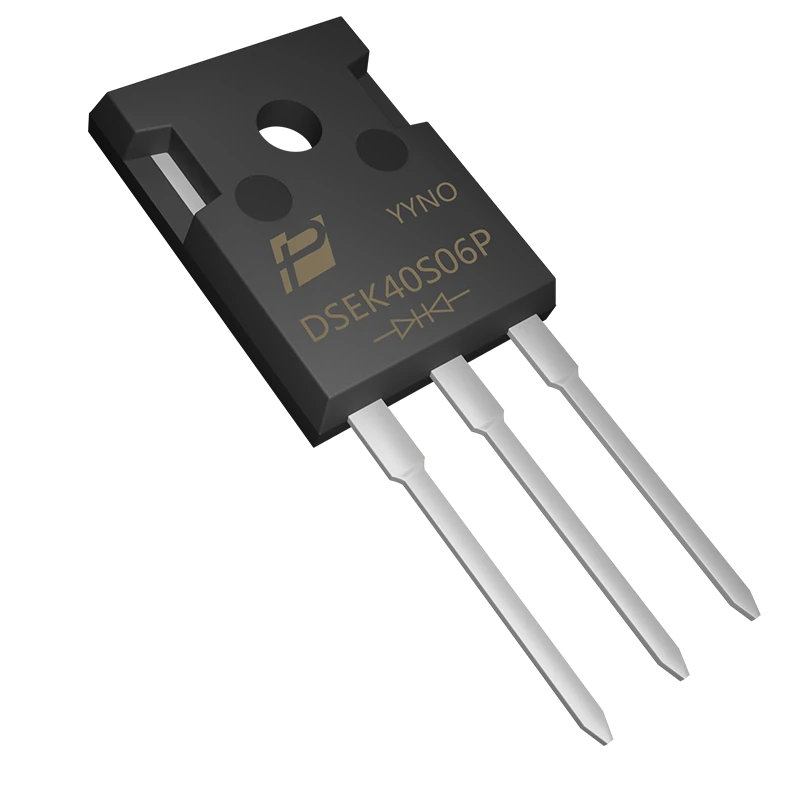
The POWERSi catalog lists DSC40065P as a 40 A, 650 V silicon-carbide Schottky rectifier and DSEK40S06P as a 40 A, 600 V ultrafast soft-recovery rectifier. These ratings identify candidates; they do not establish interchangeable parts. Check the latest model-specific datasheets, circuit topology, surge withstand, package dimensions, pinout and thermal conditions with POWERSi. In particular, the different voltage ratings require an actual reverse-voltage stress and margin review.
Do not compare the website’s typical forward-voltage figures directly: one is stated at 175 °C and the other at 125 °C, so they are not matched test points. The DSEK40S06P product page lists 1.12 V typical at 20 A and 125 °C, while its version 2.0 datasheet summary lists 1.20 V at those stated conditions. Confirm the applicable controlled specification and test basis with POWERSi, and obtain curves or measured values at the relevant current and temperature. The DSEK40S06P page specifies two 20 A common-cathode diode paths and 40 A total, while DSC40065P is a single diode; the two 40 A headings therefore are not equivalent per conducting path. The DSC40065P page also contains a separate “Rated IF” field of 20 A despite its 40 A product description. Obtain a controlled datasheet and written clarification before designing around either rating. Do not parallel the silicon diode paths without a current-sharing and thermal assessment.
| Comparison item | Silicon ultrafast PN diode | SiC Schottky diode | Decision evidence |
|---|---|---|---|
| Commutation | Stored charge contributes reverse-recovery current | Junction capacitance contributes current; no comparable minority-carrier recovery mechanism | Measure diode and switch current/voltage at the same operating points |
| Conduction | Use VF at the actual current and temperature | Use VF at the same operating point | Integrate v(t) × i(t) over a cycle |
| Stress and cooling | Verify surge, Tj, mounting and case temperature | Verify the same; check startup surge separately | Worst-case thermal and startup testing |
| Cost | Include switch, heatsink, snubber and assembly | Include higher or lower quoted part cost and all changed surrounding items | Use actual quotes and released BOM revisions |
Build a loss and temperature comparison
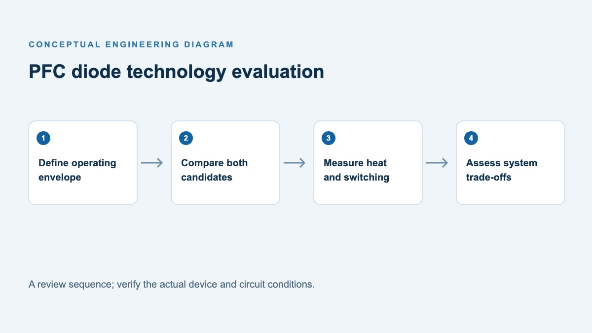
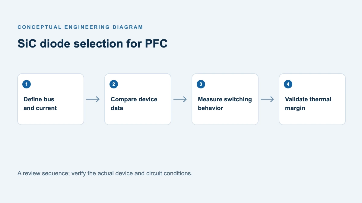
Begin with the same power-stage role, line voltage, bus voltage, switching frequency, input power, ambient temperature, heatsink and gate drive. The DSC40065P is a two-lead single diode; DSEK40S06P is a three-lead dual common-cathode device with different terminal connections, so they are not drop-in substitutes. Use a comparison board designed for the appropriate connections and ratings, or separately qualified equivalent boards; document any layout and interconnection differences and their effect on the comparison. Record diode case temperature at a defined contact point after stabilization. Also measure the switch temperature: reduced diode recovery may move the most meaningful difference into the switch. Case temperature alone is not junction temperature; estimate Tj using the appropriate device thermal model and validated power dissipation, considering coupling and transient heating.
Use oscilloscope voltage/current waveforms to integrate switching energy over an identical time window, and compare input/output power with a suitable power analyzer. Avoid adding diode loss and switch loss twice if system efficiency already includes both. For full-cycle diode conduction, calculate or integrate instantaneous diode voltage times current; a single VF multiplied by average current is only an approximation. Test low and high line, full and light load, startup, overload and the intended maximum ambient. Check device voltage overshoot and EMI, not only efficiency.
Compare the complete cost, not only the diode price
The following is a hypothetical method illustration, in arbitrary currency per unit; it is not a POWERSi quotation or a claim of measured savings:
| Cost item per completed unit | Silicon option | SiC option |
|---|---|---|
| Diode | 1.00 | 1.80 |
| Heatsink, mounting and assembly | 2.00 | 1.50 |
| Snubber and related parts | 0.40 | 0.30 |
| Recurring total | 3.40 | 3.60 |
Here the SiC part costs 0.80 more; hypothetical surrounding-item savings of 0.60 leave a recurring premium of 0.20 per unit. At 10,000 units that is 2,000 before one-time engineering, qualification, tooling, scrap, warranty or energy costs. Those surrounding savings are only valid after an approved redesign and quote; if the heatsink is unchanged, do not book a theoretical saving. If cooler operation meets a required derating or reliability target, record that separately rather than inventing a warranty benefit.
A related POWERSi article, Charger Power Modules: When SiC Should Replace FRED, addresses the replacement decision in charger modules. This article adds a repeatable boost-PFC measurement and total-cost worksheet for a silicon/SiC choice.
Support for your evaluation
Share the PFC operating envelope, measured waveforms, mounting and qualification requirements when contacting POWERSi. Review DSC40065P SiC rectifier details and DSEK40S06P ultrafast rectifier details; the components require separate suitability checks.
FAQs
Is SiC always the more efficient option?
No. Operating mode, switching frequency, conduction conditions, package and circuit design affect the result. Measure the system at the relevant points.
Can the 650 V SiC part directly replace the 600 V silicon part?
Not on voltage class alone. Verify electrical limits, surge, thermal performance, dimensions, terminal connections and qualification in the actual assembly.
Can I calculate energy savings from the datasheet alone?
Datasheets can screen candidates, but operating waveforms and whole-system measurements are needed for a credible energy estimate.
What should the supplier receive?
Share the schematic location, input and bus ranges, current waveform, switching frequency, temperature, cooling, startup surge and mechanical limits, together with requested qualification documentation.
References
- POWERSi DSC40065P data sheet and DSEK40S06P data sheet — obtain controlled revisions and resolve public-data differences.
- POWERSi DSC40065P product page and DSEK40S06P product page.
- Infineon, Design Guide: Boost Type CCM PFC.
- Infineon, CoolSiC Schottky Diodes Selection Guide.