Skip to content

PFC Boost Diode Selection by Conduction Mode
Last Updated: 2026-11-10
Quick Answer
PFC boost diode selection starts with conduction mode and commutation conditions. A silicon fast-recovery diode and a SiC Schottky diode face different loss trade-offs in continuous, critical and discontinuous operation. Establish the operating-mode map first, then compare recovery, capacitive charge, conduction and temperature under matched conditions.
Map the Mode Before Comparing Parts
In continuous conduction mode, the boost inductor current remains above zero over the switching cycle at the operating point being considered. The diode can therefore be forced from forward conduction into blocking while carrying appreciable current. In critical conduction, the controller normally starts a new cycle around the point at which inductor current reaches zero. Discontinuous operation includes a zero-current interval.
One converter can move between modes as line voltage and load change. Classify the operating points rather than assigning a single label to the entire product. Startup, line-cycle boundaries and burst operation may require separate evaluation.
Choose a Device Family for the Actual Position
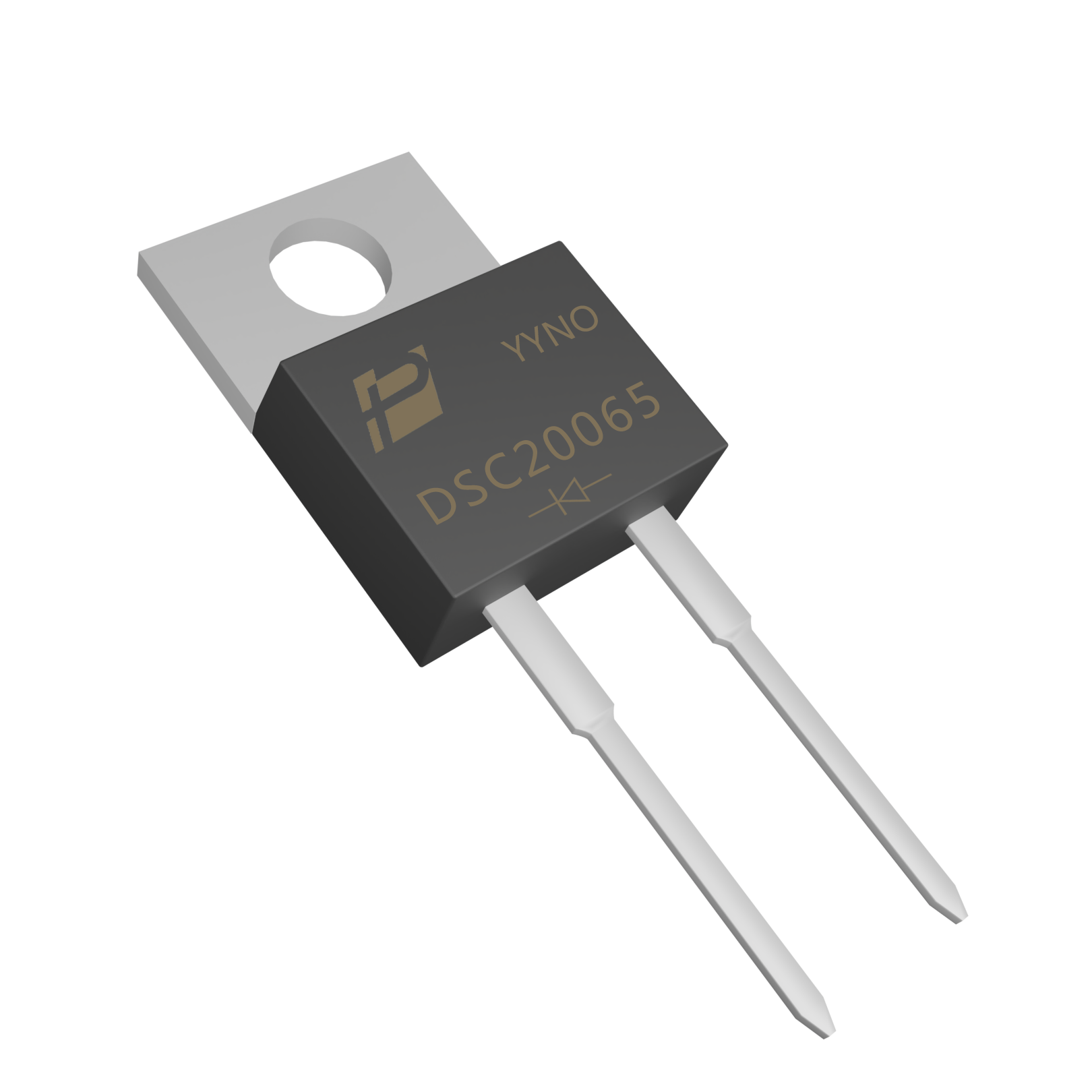
The POWERSi DSC20065 has a two-lead package with an exposed metal tab and mounting hole. It illustrates a SiC product candidate; it does not establish suitability for every bus voltage or switching frequency.
Check the actual peak reverse voltage including overshoot, current waveform and thermal mounting. A device rating is a boundary with specified conditions, not a substitute for system margin. Do not infer the required diode current rating simply by dividing output power by a convenient round number.
Understand the Hard-Commutation Penalty
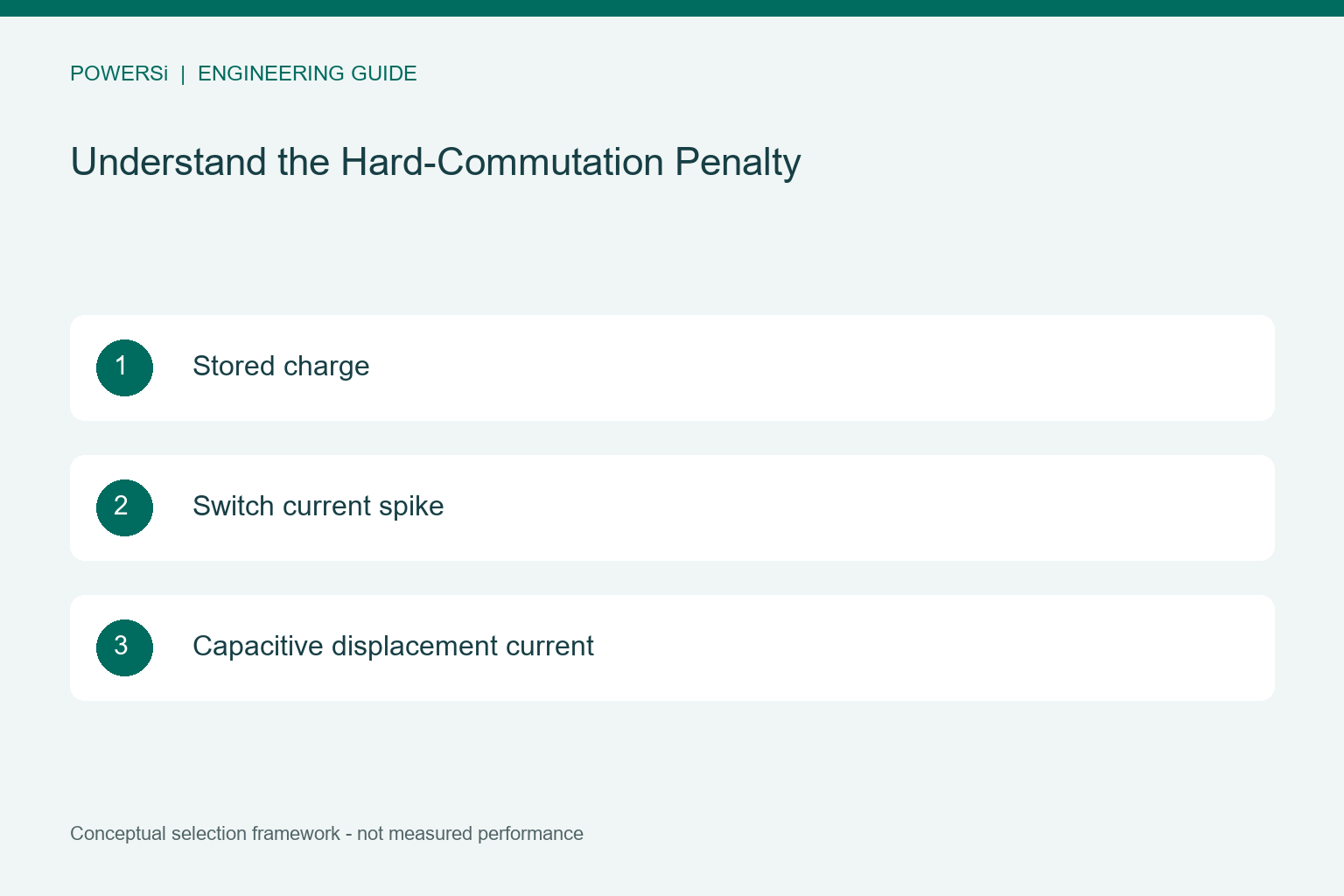
Silicon PN diodes store minority-carrier charge during conduction. During hard commutation, removing that charge can increase current stress and loss in the switching loop. SiC Schottky diodes avoid that same storage mechanism, but their junction capacitance still moves charge when voltage changes.
The Infineon CCM PFC design guide discusses this boost-diode trade-off. Its relevance is strongest when interpreted at the actual current, voltage and temperature. A short recovery-time number alone cannot describe the complete switching event.

Compare Candidates at Three Operating Regions
At low line and high load, examine the high-current conduction intervals and commutation stress. At high line and light load, examine capacitive loss, changing frequency and control behavior. At mode transitions, check whether ringing or timing changes introduce a stress that the steady-state points miss.
Use the same board, probe arrangement and temperature conditions for an A/B comparison. Measure both the diode and switching-device behavior. A cooler diode is not conclusive if the replacement increases another component’s loss or introduces unacceptable emissions.

Resolve Terminology Before Approving a Replacement
Fast recovery, ultrafast and FRED are product-family descriptions that can overlap; they are not three universally standardized performance tiers. Compare the specified charge, recovery behavior, forward characteristics and test conditions of the exact parts.
For a converter operating near zero-current diode turn-off, the practical benefit of changing technologies can differ from a hard-switched CCM case. Approve the part against the measured mode map, efficiency requirement, thermal limit and cost target. Keep the existing architecture unless the design brief actually calls for a topology change.
Key Takeaways
- Map the Mode Before Comparing Parts.
- Understand the Hard-Commutation Penalty.
- Resolve Terminology Before Approving a Replacement.
Conclusion
Choose the rectification approach from the measured operating conditions and the complete system requirements. Contact POWERSi with your circuit role, voltage and current waveforms, thermal limits and package constraints to discuss a suitable component candidate.
FAQs
Is FRED a separate material from silicon?
No. It commonly describes a fast-recovery epitaxial diode family.
Does SiC eliminate all switching current?
No. Capacitive displacement current remains.
Can one PFC stage operate in several modes?
Yes. Its mode may change with line voltage, load and control strategy.
What is the most useful comparison point?
Use the operating points that set thermal and electrical limits, plus mode transitions.
Does a lower diode temperature prove success?
No. Check total stage loss, switch stress and emissions too.