Skip to content

Flyback RCD Clamp Diodes: Fast or Ultrafast?
Last Updated: 2026-11-16
Quick Answer
Flyback RCD clamp diode selection requires more than the shortest reverse recovery time. Check how quickly the diode begins carrying the leakage-inductance pulse, how it recovers, and what reverse voltage it must block. Validate the diode, clamp capacitor, resistor and layout together across startup, line and load conditions.
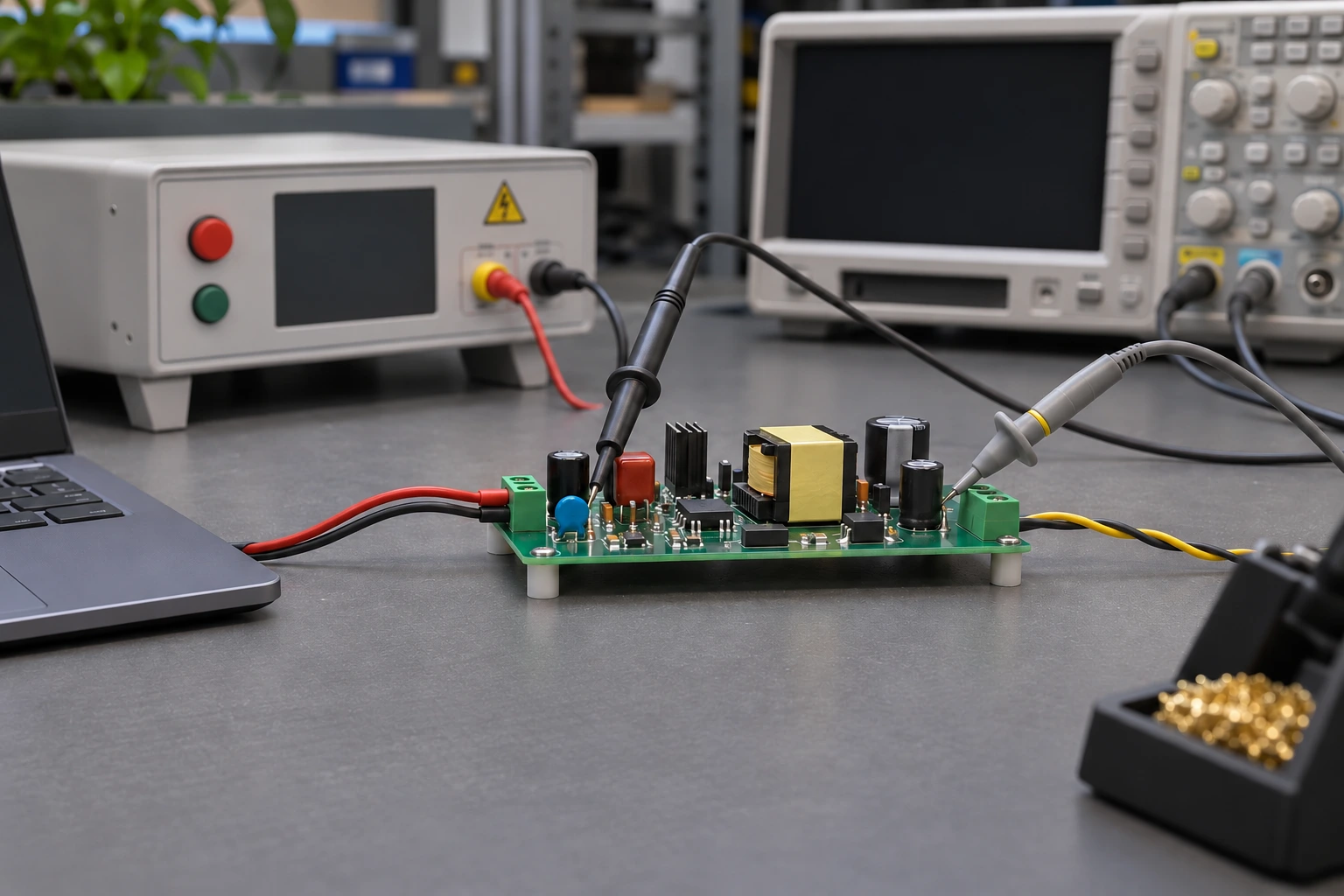
Illustrative development setup; not a wiring reference.
Separate the Primary Clamp From the Output Rectifier
In a conventional primary RCD clamp, the diode directs a turn-off transient into a clamp network. The resistor dissipates energy while the capacitor helps control the clamp voltage. This is a different job from delivering useful power through the secondary output rectifier.
Begin with the exact clamp connection and transformer polarity. The drain waveform includes the input bus, the reflected secondary voltage and the leakage-related excursion. The diode’s reverse voltage depends on the chosen connection and switching state. Neither output voltage alone nor the MOSFET voltage rating determines a suitable diode rating.
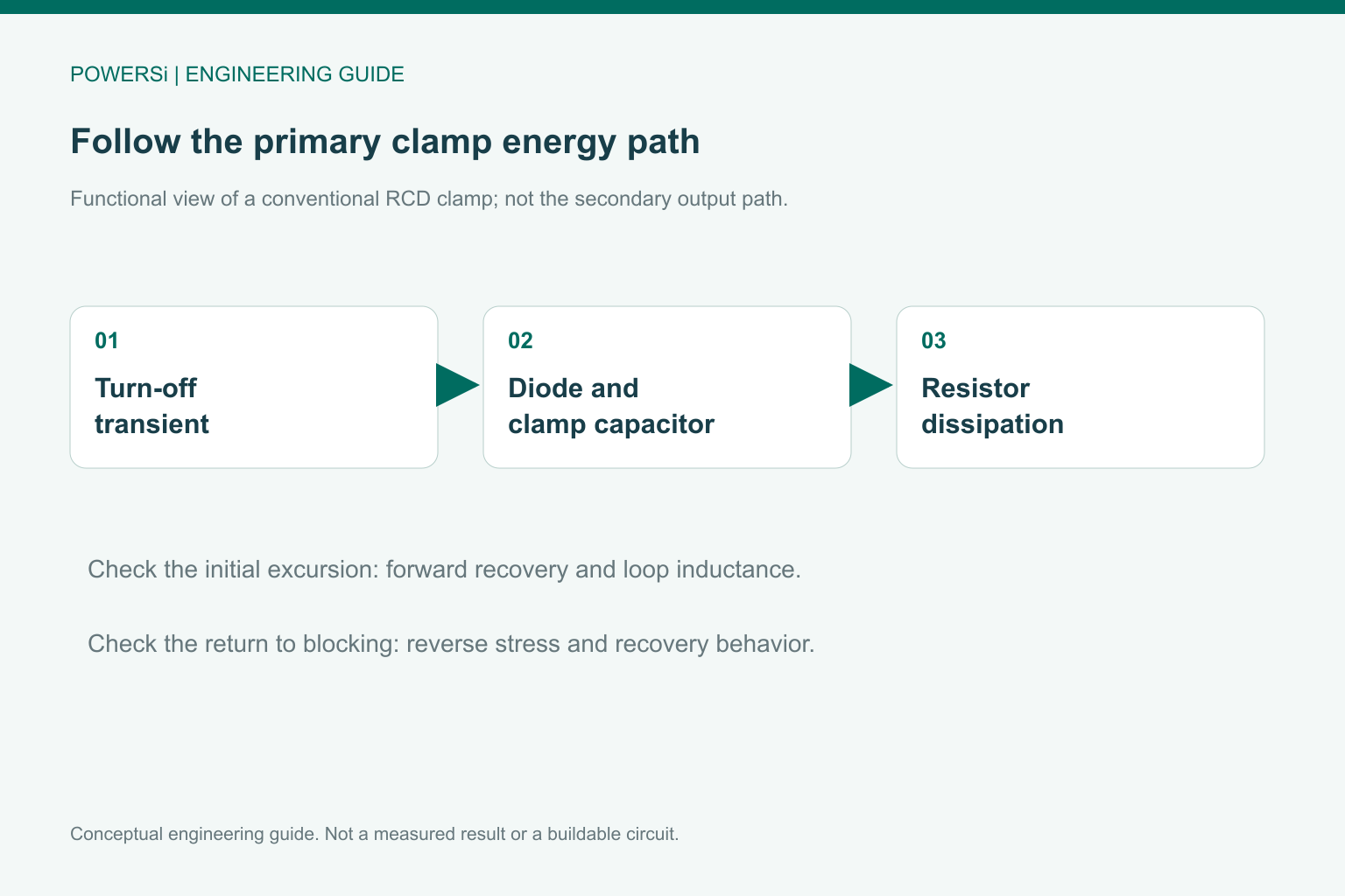
Conceptual engineering guide; no measured performance is shown.
Check Turn-On Behavior Alongside Reverse Recovery
The diode must accept the narrow current pulse when the primary switch turns off. Forward recovery and loop inductance can allow an initial voltage excursion before the clamp becomes effective. Reverse recovery matters when the diode subsequently returns to blocking, but it is not a complete description of the turn-on event.
Analog Devices discusses pulse capability and fast turn-on in its flyback snubber application article. The distinction matters when a faster advertised recovery time produces little improvement in the actual drain-voltage peak.
Compare candidates using the complete waveform. If the initial overshoot persists, investigate the clamp-loop geometry and diode forward behavior rather than assuming the recovery-time label has answered the problem.
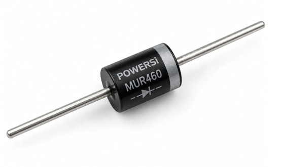
POWERSi MUR460 product example. Package appearance alone does not qualify a clamp diode.
Treat MUR460 as a Candidate, Not a Universal Clamp Part
POWERSi MUR460 is an ultrafast-recovery rectifier candidate with an axial two-lead body and a cathode band. The photograph shows that product format; a three-lead power package would represent a different physical device.
The average current in a clamp diode can be modest while the pulse current is high. Establish repetitive peak current, pulse duration, repetition rate and junction heating before selecting a model. A non-repetitive surge rating does not by itself qualify a diode for a recurring clamp pulse. Also verify the reverse-voltage envelope and the required electrical clearance around the axial leads.

Hypothetical leakage-energy estimate; not an exact RCD resistor-loss model.
Estimate Energy Before Tuning the Resistor
The expression E_leak = 0.5 × L_leak × I_pk² is a useful first estimate of the energy associated with primary leakage inductance at turn-off. Multiplying by switching frequency gives an energy-rate scale. It is not an exact universal RCD resistor-loss equation: the clamp level, reflected voltage and energy-transfer process affect the real dissipation.
For an explicitly hypothetical case, 2 µH and 3 A give 9 µJ; at 100 kHz that corresponds to 0.9 W of leakage-energy rate. These numbers are not a POWERSi test result or a finished component selection.
Check resistor power and temperature, capacitor ripple and voltage, diode stress and MOSFET drain voltage together. Lowering the clamp voltage can reduce peak drain voltage while increasing loss. A design that merely moves the hotspot from the transistor to the resistor has not completed the trade-off.
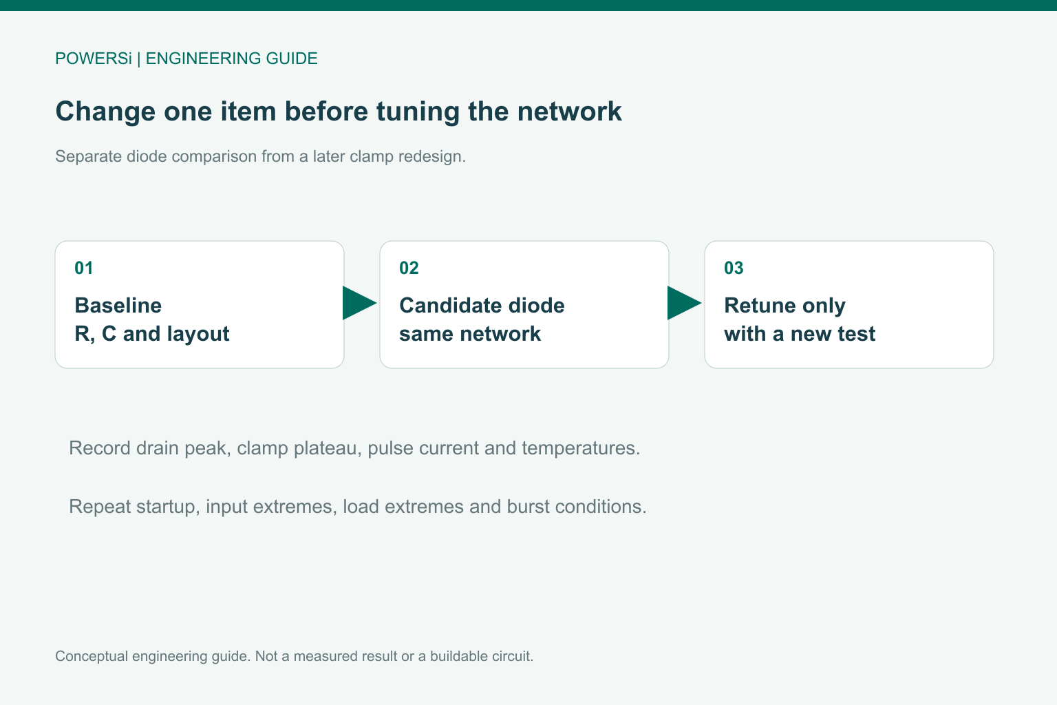
Conceptual engineering guide; no measured performance is shown.
Compare Parts With the Clamp Network Held Constant
For the first A/B trial, keep the transformer, resistor, capacitor, layout and drive settings fixed. Compare the initial drain overshoot, clamp plateau, ringing, diode current and component temperatures. Use a probing method that does not add a large measurement loop.
Evaluate startup, maximum input, load extremes and burst operation where implemented. After identifying a suitable diode, tune the network only if the project needs it, and repeat the stress checks. Fast and ultrafast are family descriptions, not a universally ordered guarantee of clamp performance. Release the exact combination that satisfies the voltage margin, loss budget and thermal limits.
Key Takeaways
- Distinguish primary-clamp requirements from output-rectifier requirements.
- Check forward turn-on and reverse blocking as well as recovery.
- Validate the diode and the entire RCD network at operating extremes.
Conclusion
Choose the clamp diode from the measured pulse and voltage envelope, then verify the network as an assembly. Share the clamp connection, transformer leakage estimate, peak current and drain capture with POWERSi when requesting an ultrafast-rectifier candidate.
FAQs
Is the RCD clamp diode the secondary rectifier?
No. The primary clamp handles a transient-energy path; the secondary rectifier supplies the output.
Does the shortest trr guarantee the lowest drain spike?
No. Forward recovery and clamp-loop inductance also affect the initial excursion.
Can IFSM prove repetitive pulse suitability?
No. A one-time surge specification has different conditions from recurring clamp pulses.
Is the leakage-energy estimate the exact resistor loss?
No. Clamp level and energy-transfer behavior affect actual dissipation.
Should the clamp resistor change during the first diode comparison?
Keep it unchanged initially so that the effect of the diode can be isolated.