Skip to content

Standby Power Debugging: Is Schottky Leakage the Cause?
Last Updated: 2026-11-10
Quick Answer
Schottky leakage can contribute to standby power, especially at elevated temperature, but it is only one possible cause. Measure the complete supply in a defined standby state, identify which paths remain energized, and isolate the rectifier contribution before changing parts. Confirm any improvement without sacrificing loaded operation or stability.
Define the Standby State First
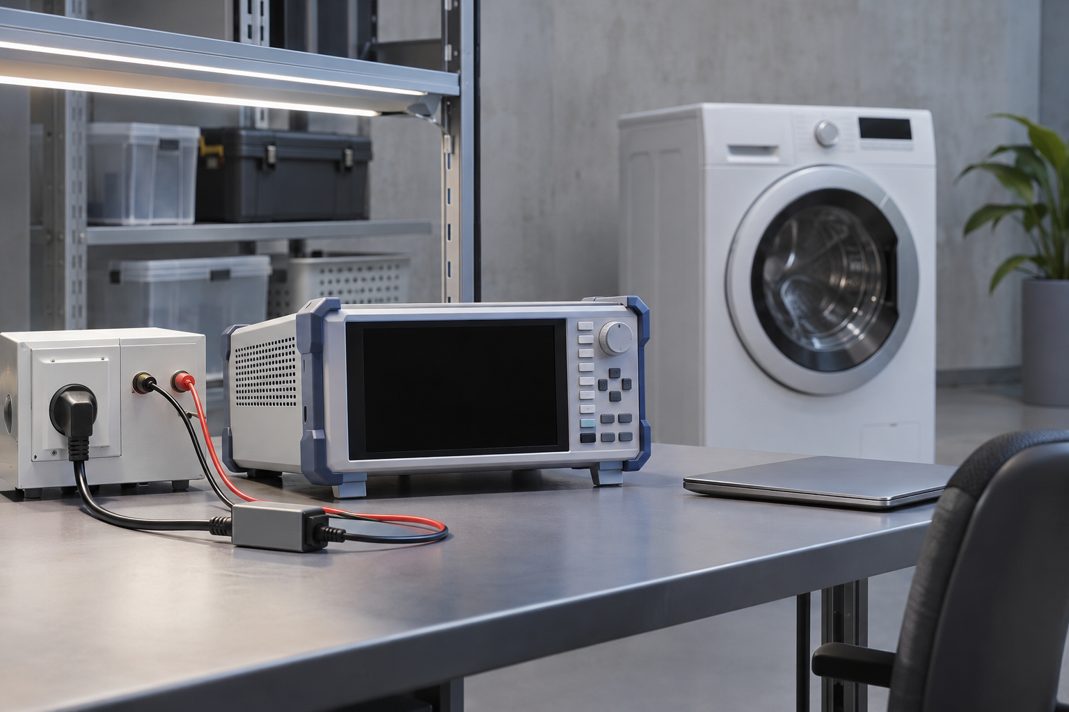
An appliance may keep its controller, communications circuit or display alive while the main load is off. Standby is therefore a system operating state, not simply zero output current. Record which rails and functions are enabled, the input condition and the time after entering that state.
Use an instrument and range suitable for low real power and the waveform being measured. Capture enough time to include burst cycles or periodic housekeeping events. A brief reading taken between bursts can underestimate average input consumption and make a component change appear more effective than it is.
Use the Product Image for Identification
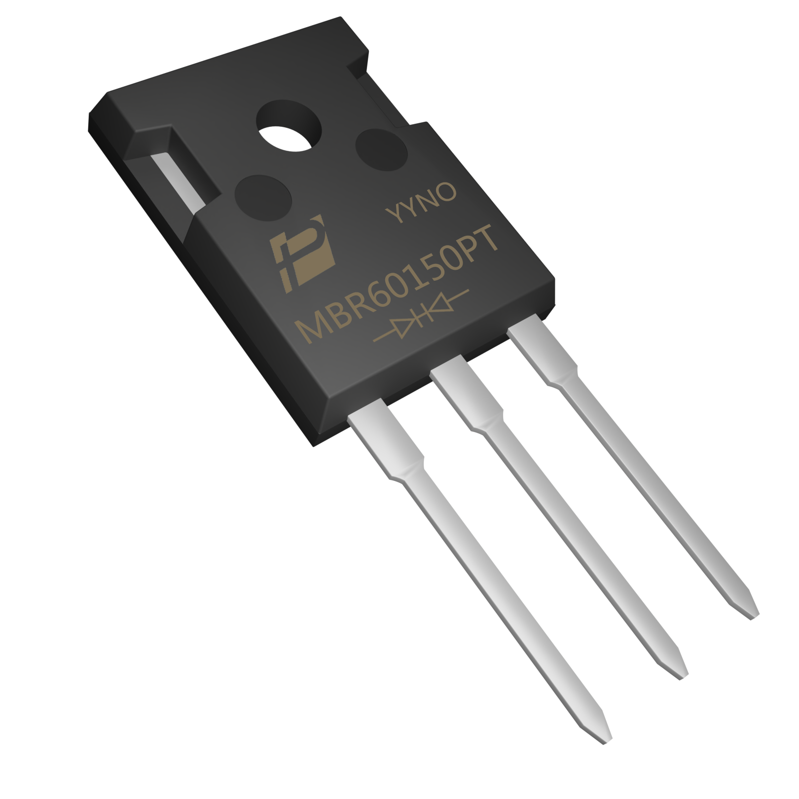
The MBR60150PT is shown as a POWERSi product example, not a claim that this particular part is the cause of appliance standby loss. The photograph establishes model and package identity; it does not provide a reverse-leakage value.
For the actual output rectifier, establish its reverse voltage, temperature and conducting duty. Compare leakage at relevant conditions, including tolerances, rather than treating a room-temperature typical value as a hot maximum. Avoid replacing a device solely because a different family advertises a lower forward drop.
Estimate the Leakage Contribution
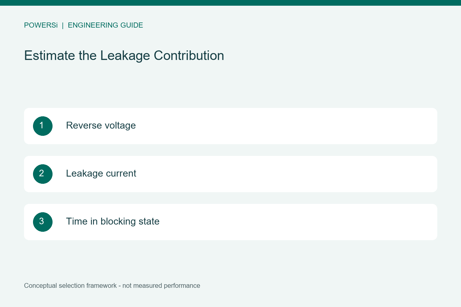
For approximately constant reverse voltage and current, reverse loss is voltage multiplied by leakage current, weighted by the fraction of time in that state. As an illustrative estimate, 50 V multiplied by 1 mA gives 50 mW during continuous blocking. These numbers are hypothetical and do not describe the pictured product.
Relate that component loss to the complete supply carefully. Changing leakage can also alter how often the controller replenishes output energy. The resulting input-power change depends on the operating mode and incremental conversion loss; it is not necessarily equal to the simple component estimate.
Separate Diode Loss From Other Paths
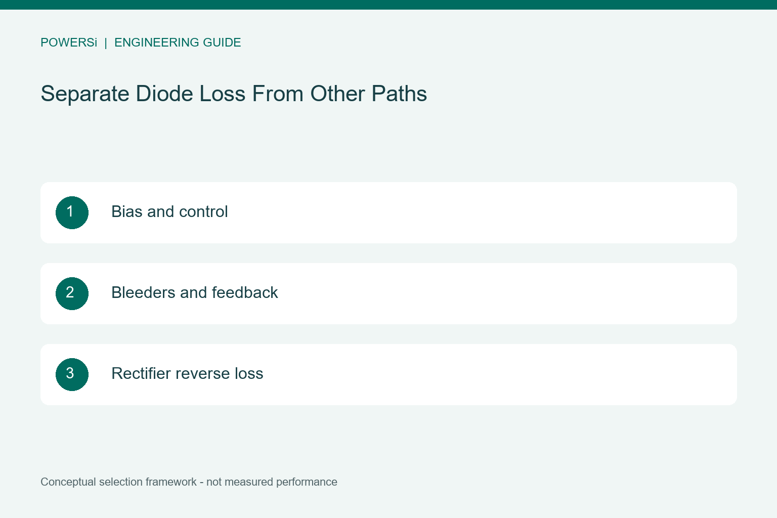
Build a standby power budget that includes controller supply, startup circuits, feedback, bleeders, snubbers and enabled loads. Inspect each candidate path without defeating the protection needed for the test. Qualified personnel should use appropriate isolated measurement methods around mains circuitry.
Compare baseline and candidate boards after reaching comparable temperatures. Leakage generally becomes more important as junction temperature rises, and reverse loss can reinforce heating. Toshiba explains this leakage and heat-balance mechanism for SiC Schottky devices; the explanation is not a numerical leakage specification for a silicon device.
Verify the Fix in Both Standby and Active Use
Repeat the standby measurement with identical firmware state, input voltage and averaging period. Confirm that the improvement exceeds measurement uncertainty and normal unit variation. Record both cold entry into standby and the transition after active operation.
Then retest active-mode temperature, output regulation, startup and load transients. A lower-leakage choice may change forward drop or capacitance. Release the replacement only when the full operating envelope remains acceptable. The useful outcome is a measured system improvement with a traceable cause, not simply a lower number in one component table.
Key Takeaways
- Define the Standby State First.
- Estimate the Leakage Contribution.
- Verify the Fix in Both Standby and Active Use.
Conclusion
Choose the rectification approach from the measured operating conditions and the complete system requirements. Contact POWERSi with your circuit role, voltage and current waveforms, thermal limits and package constraints to discuss a suitable component candidate.
FAQs
Is Schottky leakage always the largest standby loss?
No. Controller bias, bleeders and enabled loads may dominate.
Why average over several burst cycles?
A short interval can miss the energy consumed during periodic switching.
Can leakage be calculated from the photograph?
No. It requires electrical data or measurement at defined conditions.
Does lower leakage guarantee lower total loss?
No. Forward loss and changes in converter operation also matter.
What must be retested after replacement?
Repeat standby measurements and verify active-mode thermal, regulation and transient behavior.