 Skip to content
Charger Power Modules: When SiC Should Replace FRED
Last Updated: 2026-10-13
Quick Answer
SiC can improve a charger module when silicon diode recovery materially contributes to switching loss or stress. It is not a mandatory upgrade for every rectifier position. Compare the actual topology, operating range, capacitive charge, conduction loss, cooling and cost before choosing between a fast-recovery silicon diode and SiC.
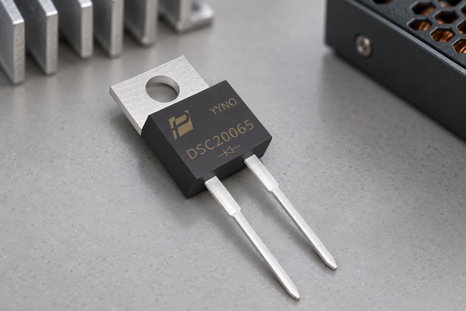
Product scene based on the supplied DSC20065 reference; application suitability is evaluated separately.
Identify the Loss Mechanism You Want to Change
A technology change should solve a measured problem. In a hard-switched boost stage, diode recovery can add current to the switch turn-on event. SiC Schottky devices avoid the minority-carrier recovery mechanism of silicon PN diodes, which can make them attractive in that location. Device capacitance still creates charging current.
Infineon’s CCM boost PFC design guide discusses the boost diode’s influence on commutation. Establish whether this mechanism dominates the module’s losses before attributing a system-efficiency target to the diode alone.
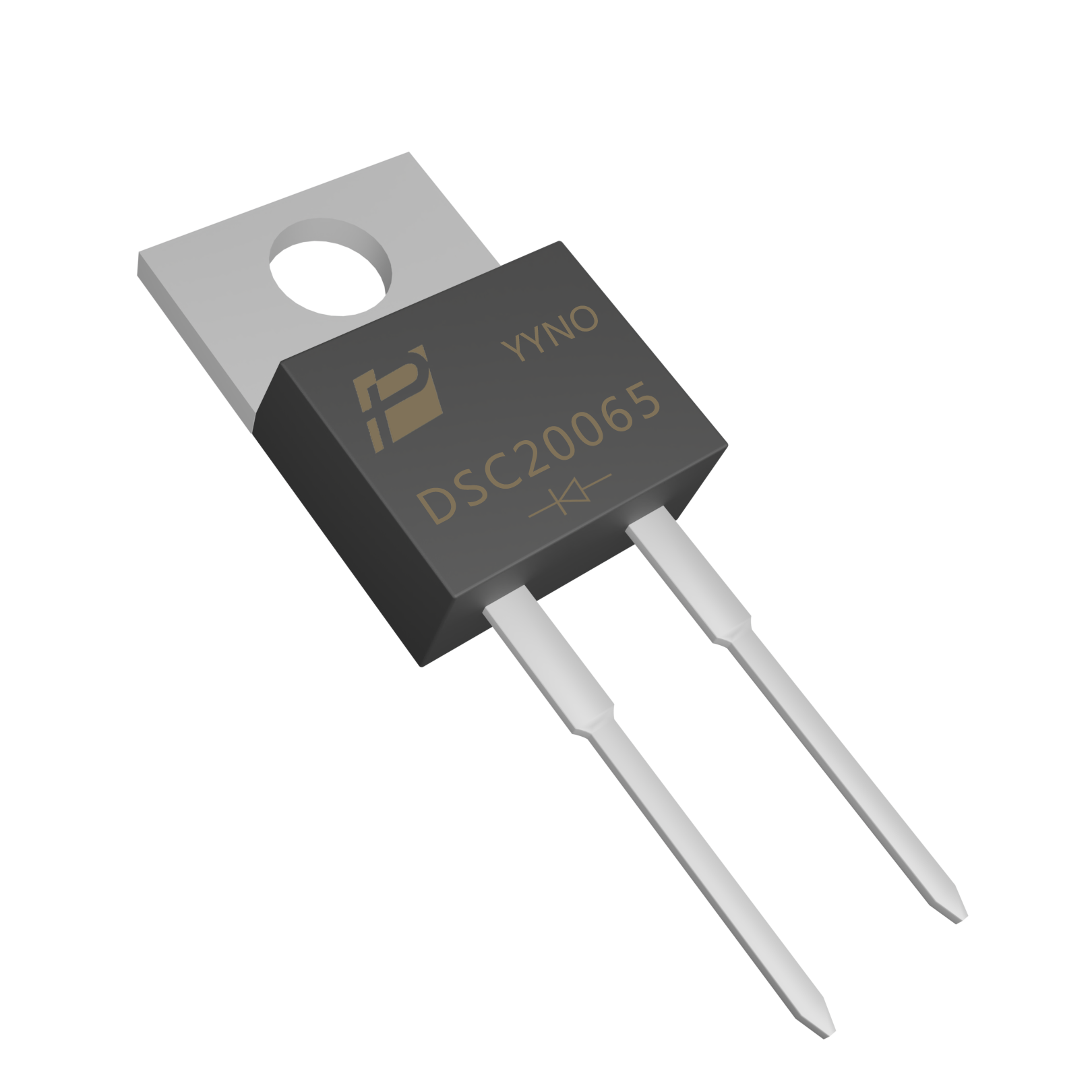
Supplied DSC20065 product reference; no system-level suitability or qualification is implied.
Start With a Defined SiC Candidate
POWERSi DSC20065 is a 650 V SiC Schottky diode in a two-lead TO-220AC package, as identified in its supplied V2 documentation. The original product image fixes the external construction used in this article. It is an example for a suitably bounded device position, not a declaration that every charging module can use it.
Measure the voltage across that position, including overshoot, before evaluating the voltage margin. Battery voltage, DC-link voltage and individual diode stress are not interchangeable numbers. If the circuit requires a higher blocking class, select a different candidate rather than rely on the word SiC to cover an inadequate voltage rating.
Recovery reduction is only one benefit.
Compare the Total Loss Budget
Use matched operating conditions for both candidates. Compare forward characteristics over temperature and current, the relevant dynamic charge and the resulting stress on the switch. Typical values are useful for initial modeling but should not replace guaranteed limits where a design boundary depends on them.
| Comparison | What a meaningful result includes |
|---|---|
| Diode conduction | Actual current waveform and hot forward voltage |
| Commutation | Switch energy, diode current and voltage overshoot |
| Cooling | Same mounting stack, airflow or coolant conditions |
| System efficiency | Repeatable input/output measurement across load |
| Economics | Component, cooling, EMI and redesign costs |
A lower diode loss does not translate directly into the same percentage improvement in whole-module efficiency. Keep the measurement boundary explicit.

Illustrative application scene; not a customer installation or a measurement result.
Check Startup, Low Load and Mode Changes
A candidate must tolerate the events the charging module actually produces. Evaluate bulk-capacitor charging paths, precharge behavior and restart conditions against the device’s own surge limits. Do not assume that every SiC diode has the same inrush capability or that a boost diode carries every startup pulse.
At light load, a controller may change frequency or operating mode, altering the value of a recovery reduction. Check ringing and emissions after any change in switching speed. Record gate-drive or snubber adjustments so the final comparison describes the released configuration rather than a component swap tested under unrelated conditions.
An upgrade needs a justified trade-off.
Keep FRED Where It Fits the Requirements
A silicon FRED can remain appropriate when its losses and switching behavior satisfy the operating envelope at an acceptable total cost. Infineon’s silicon diode portfolio illustrates that silicon technologies continue to address power-conversion applications alongside SiC.
Distinguish a diode substitution from a topology change to active rectification or a bidirectional stage. Those projects require different evaluation work. For a POWERSi inquiry, supply the original device, circuit role, switching waveform, cooling limits and acceptance targets. Choose the technology after the comparison, not before the problem has been defined.
Key Takeaways
- Choose SiC for a defined circuit problem.
- Recovery reduction is only one benefit.
- An upgrade needs a justified trade-off.
Conclusion
Compare the measured commutation problem and the complete implementation cost. Contact POWERSi with the module envelope to assess a specific FRED or SiC option.
FAQs
Must every charger module replace FRED with SiC?
No. The benefit depends on the circuit position, operating conditions and total cost.
Does a SiC diode have zero switching current?
No. Its capacitance still draws charging and discharging current.
Is DSC20065 suitable for every high-voltage charging stage?
No. Its 650 V rating must be evaluated against the actual device stress and required margin.
Can lower diode loss be quoted as equal system-efficiency gain?
No. Whole-module efficiency has a different power boundary.
When can a FRED remain the better choice?
When its measured performance meets the requirements with a favorable overall implementation cost.


