 Skip to content
Schottky High-Temperature Leakage: Assessing Thermal Runaway Risk
Last Updated: 2026-09-30
Quick Answer
Schottky high-temperature leakage can increase reverse-blocking loss as the junction becomes hotter. That additional heat can increase leakage again, creating positive feedback if the cooling path cannot establish a stable operating point. Evaluate hot leakage, reverse voltage, blocking duration and total losses together rather than selecting a device only for low forward voltage.
A rectifier that performs well on an open bench can behave differently inside a hot enclosure. The difference is not limited to forward current: a blocked Schottky junction still dissipates power through reverse leakage, and that contribution can grow with temperature.
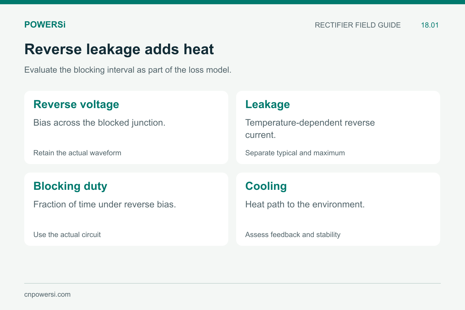
Evaluate the blocking interval as part of the loss model.
Follow the Thermal Feedback Loop
At a fixed reverse bias, leakage contributes approximately VR × IR while the junction is blocking. For a simplified waveform with a constant reverse voltage and leakage over blocking fraction Dblock, average reverse loss is approximately VR × IR × Dblock. A real switching waveform calls for an average of instantaneous voltage and current.
As temperature rises, leakage may increase and add further dissipation. Whether temperature settles or continues rising depends on the complete loss-versus-temperature relationship and the cooling arrangement. Nexperia discusses this forward-loss and leakage trade-off in its Schottky thermal-runaway application article.
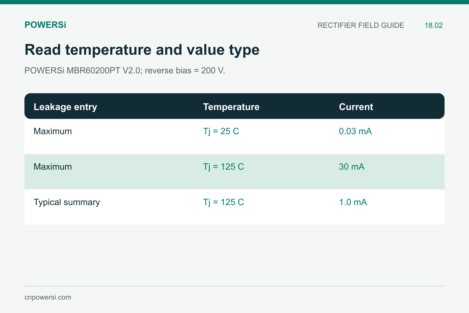
POWERSi MBR60200PT V2.0; reverse bias = 200 V.
Read Hot Limits Separately From Typical Values
The POWERSi MBR60200PT V2.0 electrical table lists maximum reverse leakage of 0.03 mA at Tj = 25°C and 30 mA at Tj = 125°C, with VR = VRRM = 200 V. The front-page summary also gives a typical 1.0 mA figure at 200 V and 125°C. The typical value and maximum limit serve different purposes.
The two maximum entries differ by a factor of 1000. This does not mean every individual sample’s leakage increases by exactly that factor. They are specification limits at two stated temperatures, not a measured temperature trajectory for one device. Nor does the lower typical value replace the hot maximum in a worst-case assessment.
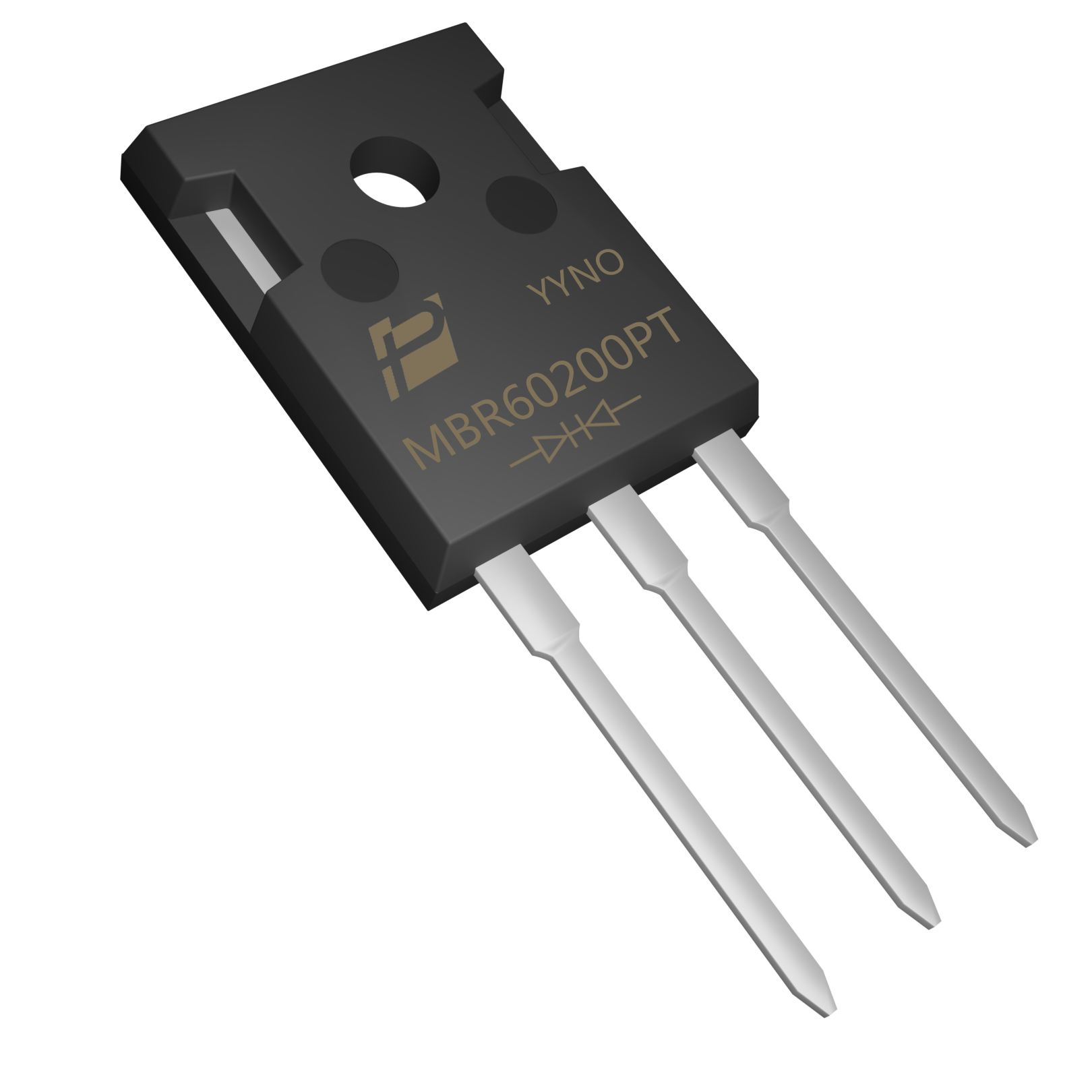
MBR60200PT original model image; the external appearance does not establish hot leakage.
Make the Loss Estimate Traceable
Applying 200 V and 30 mA during a hypothetical 50% blocking interval gives an illustrative reverse-loss term of 3 W. Using 1.0 mA instead gives 0.1 W for the same assumed interval. The comparison shows why the selected leakage value matters.
These are calculations using stated values, not measured package dissipation or a guaranteed operating point. Keep the dual-diode configuration and the supplier’s current scope consistent when building a complete package model. Include the other junction and forward or switching losses as required by the circuit.
Do not extrapolate the 125°C leakage limit to the device’s maximum junction temperature. A temperature rating does not imply that the same leakage applies throughout the range. Obtain appropriate temperature-dependent evidence for the intended operating point.
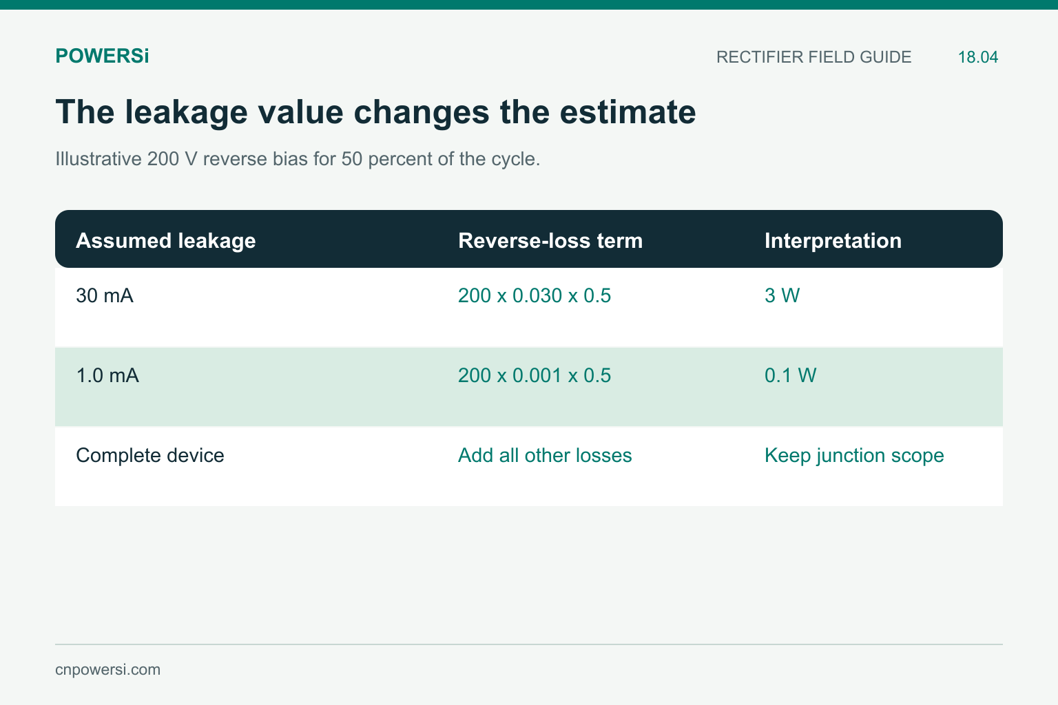
Illustrative 200 V reverse bias for 50 percent of the cycle.
Check Stability, Not Just One Temperature Estimate
A single calculation made with cold leakage can miss the feedback. Re-evaluate losses as the estimated junction temperature changes, using appropriate hot characteristics and a thermal model of the actual assembly. A rising-temperature test should run long enough to establish whether the operating point settles under the intended conditions.
Observe input voltage, reverse duty, load, case temperature and airflow together. Case temperature alone does not measure the junction temperature. A sudden leakage increase can also result from electrical damage; it should not automatically be attributed to the normal temperature characteristic.
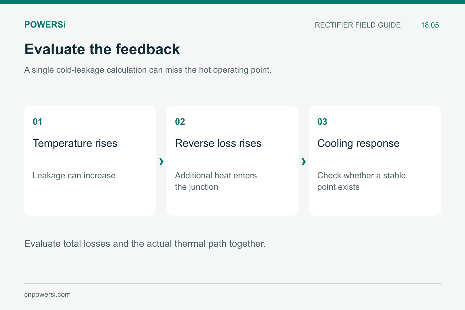
Evaluate total losses and the actual thermal path together.
Reduce the Risk at the Circuit Level
Possible changes include a better cooling interface, lower reverse stress, reduced blocking duration where topology permits, or a candidate with a better hot-leakage trade-off. Compare any increase in forward loss or other design costs at the same operating point. A lower VF device is not automatically the cooler choice over the whole cycle.
For sample approval, include hot reverse-bias behavior as well as forward conduction. Capture the operating conditions and temperature history so that purchasing decisions are tied to a repeatable test, not just a room-temperature reading.
Key Takeaways
- Reverse leakage adds heat during the blocking interval.
- Typical and maximum leakage cannot be interchanged.
- Evaluate thermal feedback with the whole-cycle loss model.
- Keep the test voltage, temperature and duty attached to every comparison.
Conclusion
Treat hot leakage as an operating loss, not a minor footnote. For a POWERSi Schottky inquiry, provide reverse voltage, blocking duty, current waveform and cooling conditions so that the comparison addresses the actual thermal requirement.
FAQs
Can a blocked diode generate heat?
Yes. Reverse voltage multiplied by leakage current produces loss during the blocking interval.
Does the maximum leakage ratio describe every sample?
No. Limits at separate temperatures do not define the measured trajectory of every device.
Can I use a typical leakage figure for a worst-case limit?
Not as a guaranteed bound. Keep typical behavior and specified maximum values distinct.
Does maximum junction temperature define leakage at that temperature?
No. Leakage needs its own stated voltage and temperature conditions.
Is a lower forward drop always thermally better?
No. Compare forward, reverse and dynamic losses with the actual cooling arrangement.


