Skip to content

Last Updated: November 5, 2026
Key Engineering Takeaways
- Calculate average, RMS and peak current through each actual diode branch.
- Confirm per-branch and total-package ratings with the specified temperature and waveform.
- Assess reverse-voltage stress, current sharing and the installed thermal path.
Quick answer
To select a Schottky diode for a switching power supply, first determine the current through each diode over the entire switching period. Compare its average, RMS and peak values with the applicable data-sheet limits and conditions; then verify reverse-voltage stress and the installed thermal path. A package with two diode junctions has two separate current paths, even if the headline current is stated as a device total.
This guide focuses on the current waveform and the physical connection of a dual diode. For the broader trade-off between forward drop and other rectifier choices, see Schottky Diodes for Low-Voltage, High-Current Rectification.
Begin with the current through the actual junction
A power supply’s output current is not always the current that flows in each rectifier. In a flyback converter, for example, the secondary diode carries a pulse while the primary switch is off; in discontinuous operation, its current can return to zero before the next switching cycle. A full-wave secondary may distribute current between two paths on alternate intervals. The waveform depends on topology, operating mode, line and load. TI’s flyback design guide uses a 10 W example to explain the corresponding peak, RMS and average rectifier stresses; it is a waveform reference, not a validation of a 60 A dual-diode application.
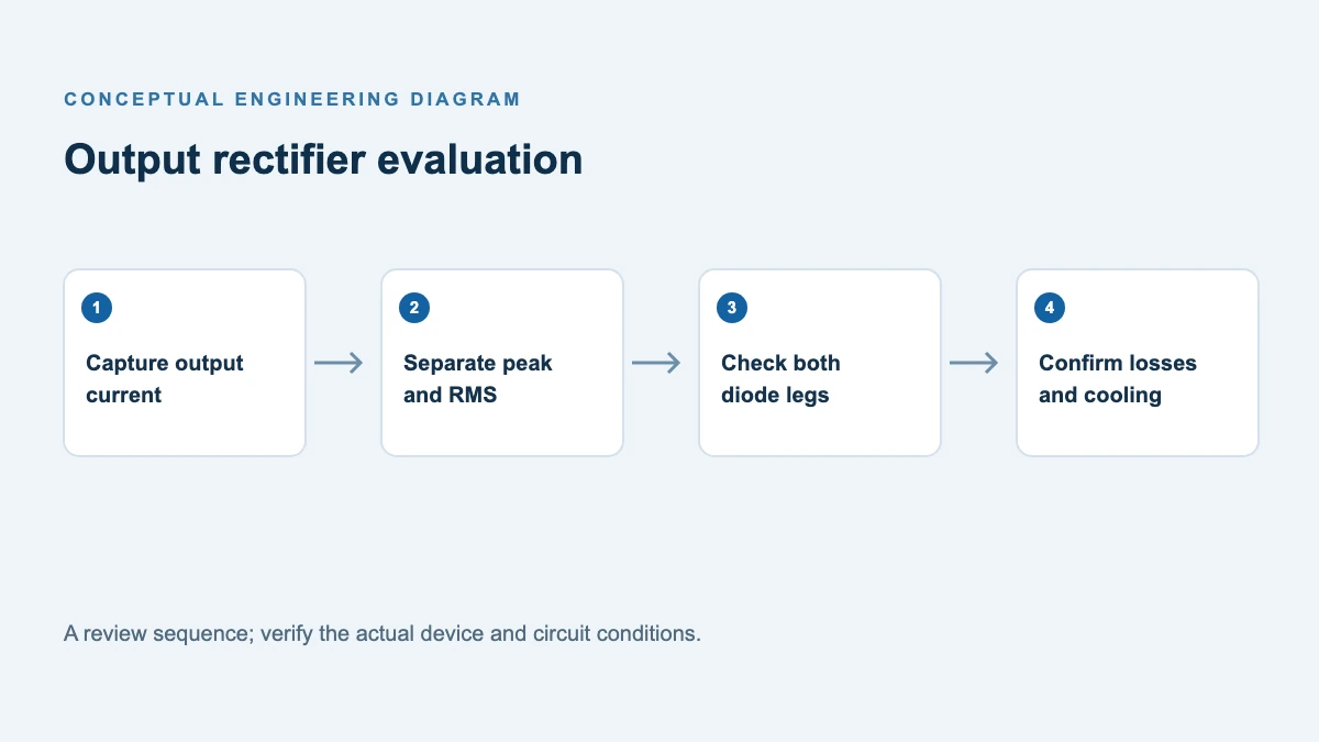
Capture or calculate current for each branch at the design corners: minimum and maximum input, full and light load, startup and load transients. Include frequency and duty-cycle changes. Ask whether the data-sheet current rating refers to a junction or the complete package, and which case temperature and cooling arrangement make that rating possible.
| Quantity | What it describes | Design use |
|---|---|---|
| Average forward current | Mean current over the full cycle, including zero-current intervals | Compare with the properly conditioned average-current rating; estimate loss with the actual forward-voltage curve. |
| RMS forward current | Square root of the mean of current squared over the full cycle | Supports waveform-dependent resistive-loss and interconnect heating estimates; it is not interchangeable with average rating. |
| Peak and pulse duration | Maximum repetitive current and how long it lasts | Check repetitive pulse limits and curves, plus startup and fault stresses separately. |
A worked pulse example
Assume an ideal rectangular current pulse of 20 A for 25% of each cycle, and zero otherwise. The full-cycle average is 20 × 0.25 = 5 A; the RMS value is 20 × √0.25 = 10 A; the peak is 20 A. The output load and a diode branch would have that same 5 A average only if the circuit makes the branch the sole steady-state path delivering output charge.
These are illustrative waveform values, not ratings of any POWERSi device. A real flyback pulse is often triangular or trapezoidal, so integrate the measured waveform rather than inserting its peak into a rectangular approximation. Estimate conduction loss as the cycle average of instantaneous forward voltage times current, using a curve at the relevant junction temperature. If only a fixed approximate forward voltage is justified, multiply it by average forward current; do not substitute RMS current into that simplified expression.
Interpret a dual common-cathode device
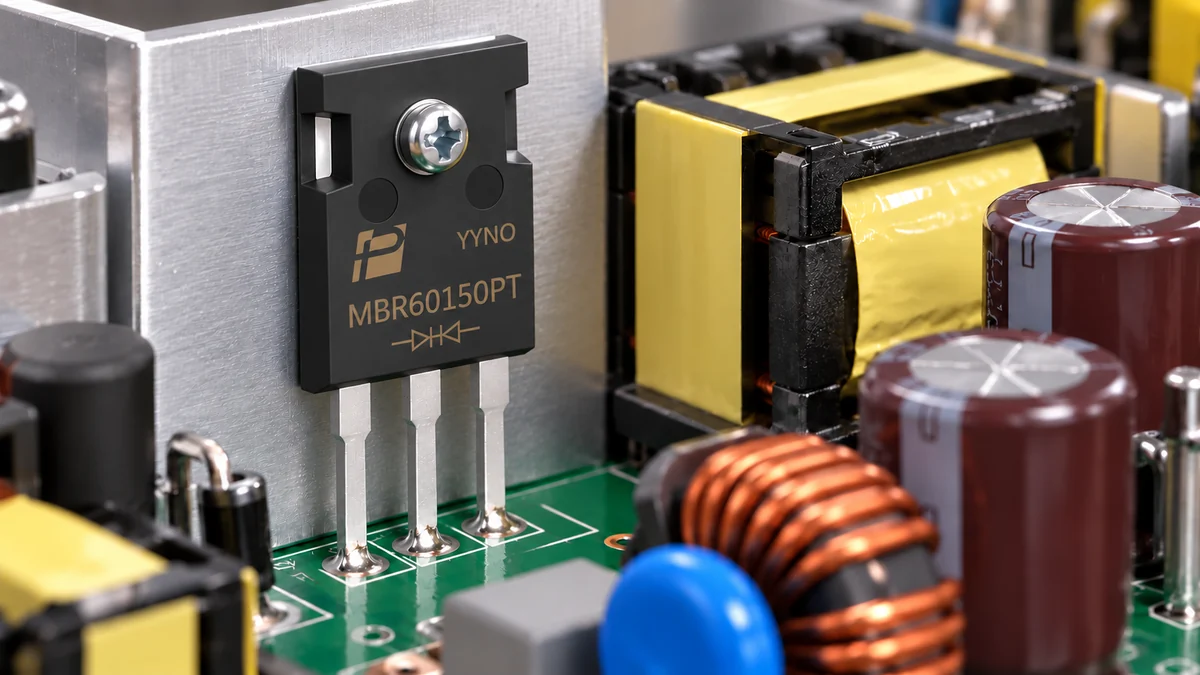
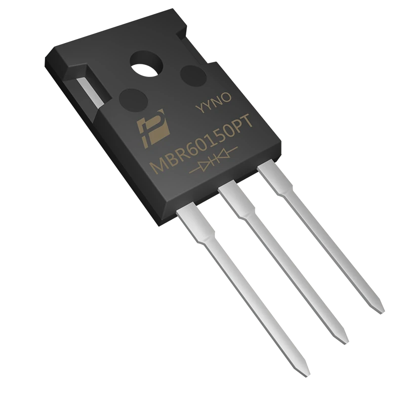
The POWERSi MBR60150PT is a 150 V dual common-cathode Schottky rectifier in TO-247AD. Its product page describes two 30 A diode paths and a 60 A total device rating. That total does not authorize 60 A through one junction. Determine which anode conducts at each interval and check each branch against its own limits and derating.
The public product page and its linked version 2.0 PDF list different forward-voltage, surge-current, junction-to-case thermal-resistance and reverse-leakage fields. For example, the page specifies a 0.95 V maximum forward voltage at 30 A and 25 °C, while the PDF lists 0.92 V at the same stated conditions. The page gives a 300 A, 8.3 ms surge per diode; the PDF gives 400 A, 8.3 ms without clearly stating the same per-diode basis in that rating row. The 25 °C leakage fields also differ, but the page summary does not state enough test conditions to establish an equivalent comparison. Do not treat these fields as interchangeable limits: obtain the controlled datasheet revision and written clarification of the test conditions for the exact order code before finalizing electrical, surge or thermal calculations.
If both branches are intended to share current in parallel, account for differences in junction forward characteristics, lead and PCB resistance, temperature and transient current distribution. A shared package does not prove equal instantaneous or average sharing. Measure both branch currents where practical and check the combined package thermal limit. Follow the verified pinout and account for the tab potential when selecting any electrical insulation and mounting hardware.
Close the electrical and thermal checks
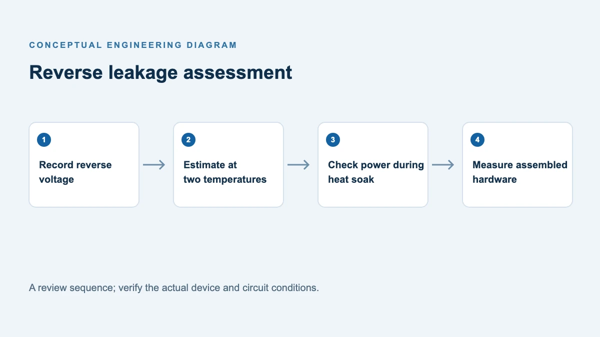
Reverse voltage must include the actual switching waveform, including overshoot and ringing, with the project’s design margin. Add forward conduction, reverse leakage and relevant switching or capacitive losses to the heat budget. For a single active junction, a first steady-state estimate is junction temperature ≈ case temperature + junction dissipation × junction-to-case thermal resistance, provided the thermal resistance and measured case location apply to that condition. If both junctions conduct, include thermal coupling and the package’s common heat path using a suitable manufacturer model; adding both powers to a single-junction resistance is not automatically valid. The heatsink, interface and time-dependent transients also need separate assessment.
Measure case or heatsink temperature under the worst credible operating conditions and compare against the manufacturer’s derating curves. A case measurement is not a direct measurement of junction temperature. Verify surge and repetitive pulses separately; a non-repetitive surge limit is not a continuous-current rating.
Build a branch-current measurement record
Choose a measurement point that captures one junction’s current without moving the original return path. If the two anodes are connected together on the board, separating them merely to insert a probe can change the inductance and current distribution. A purpose-designed fixture, a low-inductance shunt with an appropriate differential measurement, or a suitably rated current probe may help, but compare the instrumented circuit with the original switching waveform. Do not regard a changed waveform as the unmodified product’s current. Record the probe bandwidth, offset, polarity, measurement location and the number of cycles used in the calculation.
For each input and load corner, save a common time base containing branch current, diode voltage, converter mode and case temperature. Calculate the mean of forward current, its RMS value and the largest repetitive peak over whole representative switching cycles. Keep startup, overload and restart captures in a separate record: their pulses may not be repetitive steady-state events. If a converter enters burst mode at light load, capture a complete burst and quiet interval; calculating an average over only the active pulses would overstate the long-term average and conceal the burst envelope. Check the data-sheet averaging period and its specified waveform before comparing a calculated number with a rating.
| Record for each operating point | Entry to preserve |
|---|---|
| Electrical conditions | Input range, output load, frequency or burst state, branch and duty cycle |
| Current evidence | Average, RMS, repetitive peak, pulse duration, capture file and probe method |
| Thermal evidence | Ambient, case measurement location, mounting, interface and stabilization time |
| Decision | Applicable data-sheet row, revision, limit and margin, including unresolved conditions |
Use peak current and duration to find the applicable repetitive operating information; a peak value by itself is not an energy or thermal rating. If the controlled data sheet does not specify a relevant repetitive pulse limit, do not substitute the single-surge figure. Ask the manufacturer how to assess the waveform or obtain additional characterization, then verify the resulting design in the assembled converter. A measurement record makes that request specific and lets engineering and purchasing evaluate the same configuration.
Support for your evaluation
Review the MBR60150PT dual Schottky rectifier details and its applicable specifications. For an evaluation, contact POWERSi with the branch waveforms and mounting conditions and request the current controlled data sheet.
FAQs
Is a diode with a 30 A rating always sufficient for a 20 A output?
No. Determine each branch’s waveform, relevant data-sheet condition, peak, temperature and cooling. An output value alone does not establish device suitability.
Should I compare diode RMS current directly with its average-current rating?
No. They measure different quantities. Use the metric and conditions specified by each rating or curve, and use RMS when it is appropriate for a resistance-related loss calculation.
Can I parallel the two branches for the total package rating?
Only after verifying the permitted connection, current sharing and package thermal limits across conditions. The total rating does not guarantee equal branch current.
What information should I send to a supplier?
Provide the topology and branch connections, peak and average currents, current waveform, reverse-voltage waveform, switching frequency, maximum ambient and case temperatures, and cooling method.
References
- POWERSi MBR60150PT linked data sheet — reconcile the public documents and obtain the controlled revision for the order code.
- POWERSi MBR60150PT product page — device configuration and headline ratings.
- Texas Instruments, 10-Watt Flyback Converter Using the UCC3809 — output diode waveform and current stress.
- Texas Instruments, Understanding Inverting Buck-Boost Power Stages — diode selection and thermal considerations in a different topology.