 Skip to content
Power Supply EMC Troubleshooting: Is Rectifier Recovery Too Abrupt?
Last Updated: 2026-10-06
Quick Answer
Rectifier reverse recovery can contribute to power supply emissions when an abrupt current transition excites parasitic inductance and capacitance. It is one possible cause, not a complete EMC diagnosis. Correlate the switching event with the emission, control the measurement setup, and compare targeted changes before attributing a failure to diode recovery alone.
An emissions peak does not identify the responsible component by itself. Several switching edges can repeat at the same frequency, and noise can travel through more than one path. Replacing the rectifier immediately may change the symptom without revealing the coupling mechanism.
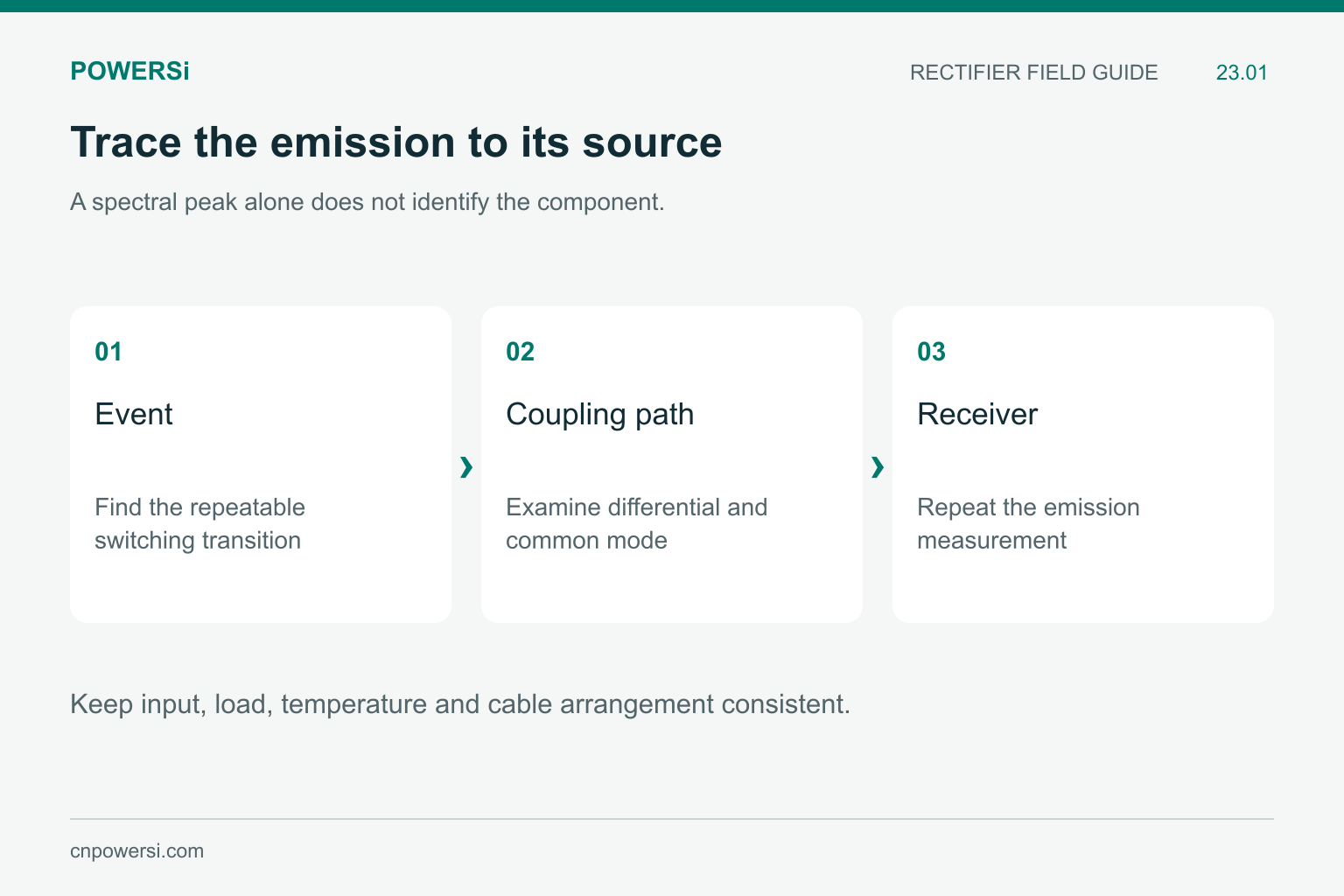
Keep input, load, temperature and cable arrangement consistent.
Identify the Event Behind the Emission
Record the operating condition at which the failure occurs: input voltage, load, operating mode and temperature. Compare the troublesome spectral region with switching-node and current measurements. Look for repeatable timing relationships, while recognizing that a time-domain correlation alone does not prove the complete source-to-receiver path.
Distinguish differential-mode current circulating through conductors from common-mode current returning through parasitic paths. A diode-loop change can affect either indirectly, but each requires a different understanding of the coupling route. Keep cable placement and the test arrangement consistent during comparisons.
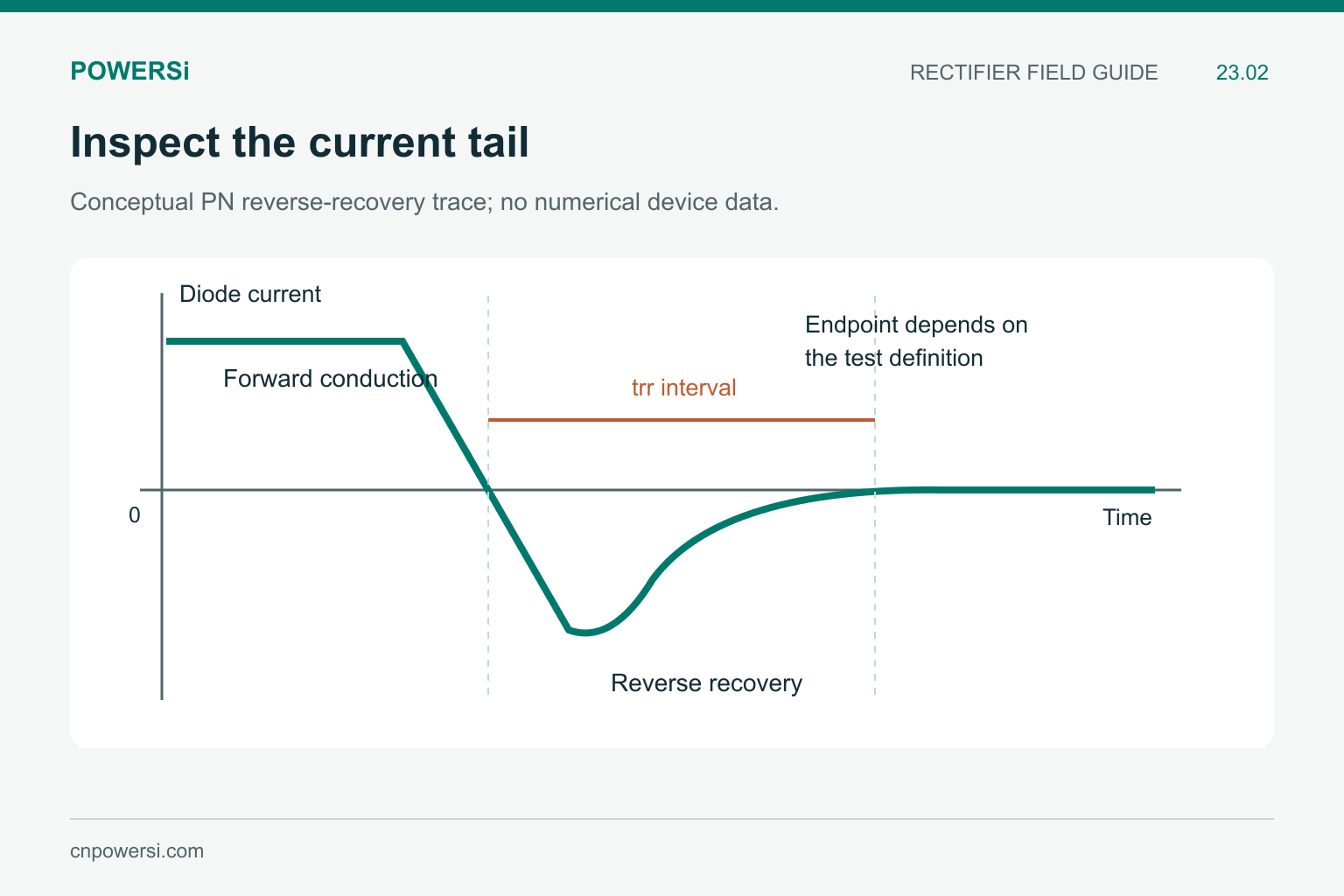
Recovery duration alone does not describe tail shape or circuit ringing.
Examine the End of Recovery
In a recovering PN diode, the return of reverse current toward zero can be gradual or abrupt. The combination of rapid current change and parasitic inductance can produce voltage overshoot and oscillation, as explained in STMicroelectronics AN5028.
The relation v = L × di/dt helps explain the sensitivity. As a magnitude-only illustration, 20 nH with a 100 A per microsecond current change gives 2 V. This is not a prediction of the full node overshoot: distributed inductance, capacitance, clamping and the actual waveform determine the circuit response.
Compare the tail shape and ringing, not just trr. Two timing entries can use different conditions or endpoints. Even equivalent durations do not specify equal recovered charge, peak reverse current or high-frequency spectral content.
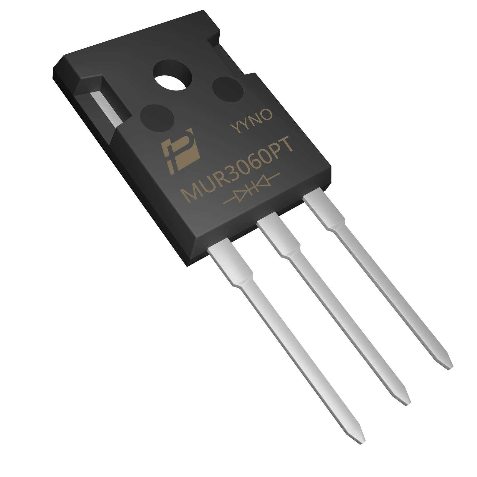
MUR3060PT original model image; a 50 ns maximum recovery entry does not establish system EMC performance.
Check What the Product Number Actually Says
POWERSi MUR3060PT V2.0 lists a maximum trr of 50 ns at Tj = 25°C, IF = 0.5 A, IR = 1 A and Irr = 0.25 A. That entry identifies a particular recovery test. It is not an EMC compliance result and does not quantify softness in the finished assembly.
Do not label a product “too hard” from this number alone. Obtain a waveform under the relevant commutation conditions and compare it with the circuit’s allowable stress and noise. Gate-drive behavior, temperature and layout can change the observed result even when the diode part number stays the same.
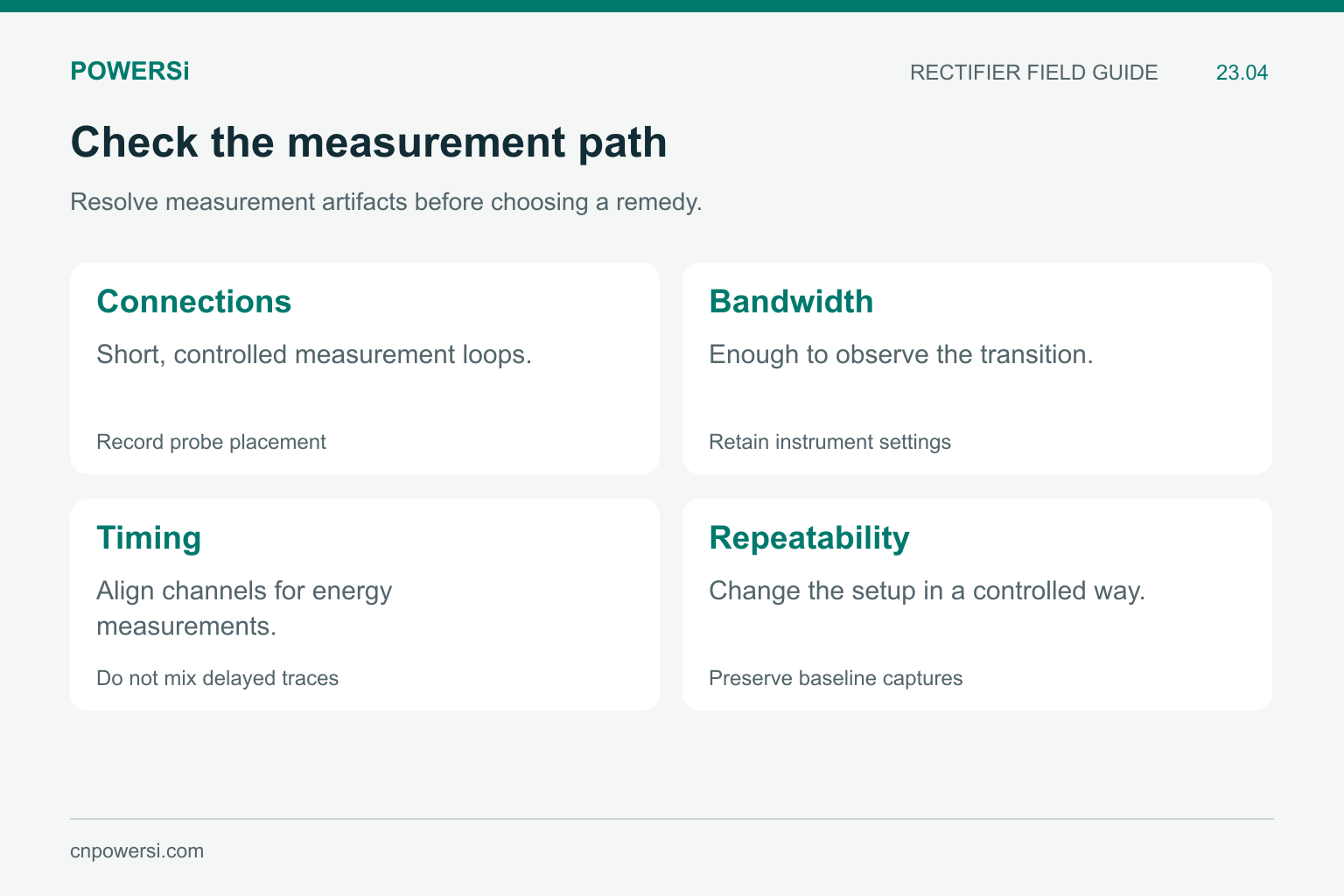
Resolve measurement artifacts before choosing a remedy.
Remove Measurement Artifacts Before Redesign
Use a suitable differential voltage measurement and current probe or characterized sensing method. Keep connections short and document bandwidth and probe placement. A long measurement loop can introduce ringing, while insufficient bandwidth can conceal a real transition.
Repeat the capture with a controlled setup change to assess sensitivity to the probe arrangement. If the waveform changes substantially because of the measurement connection, resolve that uncertainty before making a component decision. Keep the original capture and settings so that later changes remain comparable.
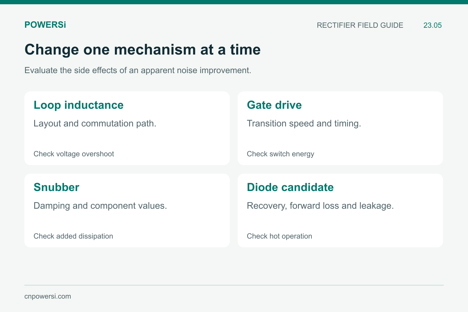
Evaluate the side effects of an apparent noise improvement.
Change One Mechanism at a Time
| Candidate change | What to evaluate alongside emissions |
|---|---|
| Reduce commutation-loop inductance | Overshoot, current paths and physical placement |
| Adjust turn-on drive | Switching energy, timing and component temperature |
| Add or tune a snubber | Damping, resistor dissipation and repetitive voltage |
| Test another rectifier | Recovery waveform, conduction loss and hot operation |
Establish a baseline, make one controlled change, then repeat at the original operating point. Check other loads and temperatures after an improvement appears. A quieter result at one point can hide a loss penalty or a worse operating corner elsewhere.
Bench spectrum comparisons are useful for diagnosis. Final acceptance still belongs to the applicable product test method and required operating configurations. Avoid turning a lower oscilloscope ringing amplitude into a claim of certified compliance.
Key Takeaways
- Treat recovery as a candidate noise source, not an automatic diagnosis.
- Connect the event, coupling path and measured emission.
- Inspect waveform shape and measurement artifacts.
- Recheck temperature and switching loss after a noise reduction.
Conclusion
An effective EMC investigation connects a physical event to a repeatable measurement. Share the baseline waveforms, operating conditions and emission band when evaluating POWERSi rectifier options, and judge the candidate in the complete switching assembly.
FAQs
Does a short trr guarantee low emissions?
No. Recovery shape, charge, parasitics and coupling paths also influence emissions.
Can a softer diode guarantee EMC compliance?
No. Compliance is a system result evaluated under the applicable test method.
Why check the probe connection?
The measurement loop can introduce artifacts or alter the observed ringing.
Is reducing gate-drive speed always beneficial?
It can reduce some transients, but may increase switching loss or alter timing. Evaluate both effects.
Does a cleaner bench waveform finish the investigation?
No. Confirm emissions and component stress across the required operating conditions and final test configuration.


