 Skip to content
Hard-Switching Diode Selection: How to Compare FRED and Ultrafast Parts
Last Updated: 2026-10-06
Quick Answer
Hard-switching diode selection requires a comparison of recovery behavior, conduction loss and circuit stress at the intended operating point. FRED and ultrafast are overlapping descriptions, not opposing quality grades. A soft-recovery candidate is worth testing when commutation causes ringing or switch loss, but the exact device and test conditions determine the result.
A converter can run at the same switching frequency with very different diode stresses. Load current, bus voltage, junction temperature and the switch’s turn-on behavior determine what happens during commutation. A purchasing instruction that simply asks for a FRED leaves those requirements undefined.
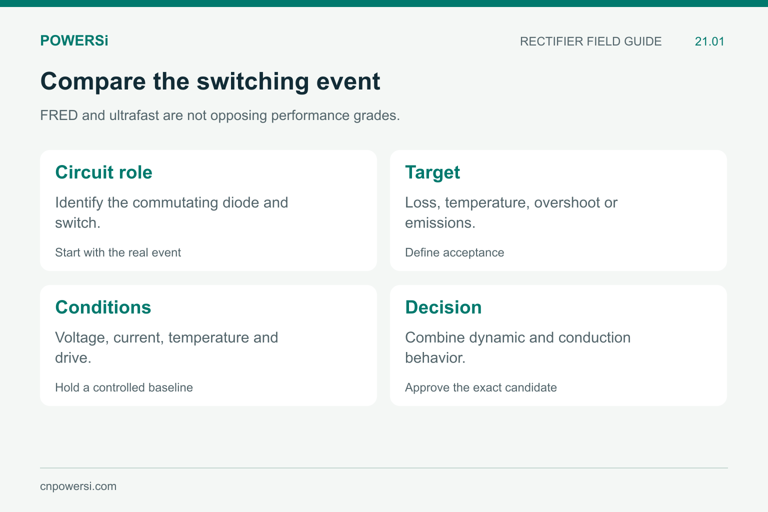
FRED and ultrafast are not opposing performance grades.
Start With the Switching Event
In a typical hard-switched freewheeling arrangement, turning on the active switch forces the conducting diode toward reverse bias. A silicon PN diode can carry reverse recovery current during this transition. The switch must handle the resulting current as well as the load-related current.
STMicroelectronics treats diode recovery and the associated switch turn-on loss together in AN5028. This is why a diode comparison should include the switching cell, rather than only diode temperature or recovery time.
First identify the actual problem: excessive switch heating, diode heating, voltage overshoot or an emissions peak. Give it a measurable acceptance target. A candidate that reduces ringing but increases total loss beyond the thermal budget has not solved the complete design problem.
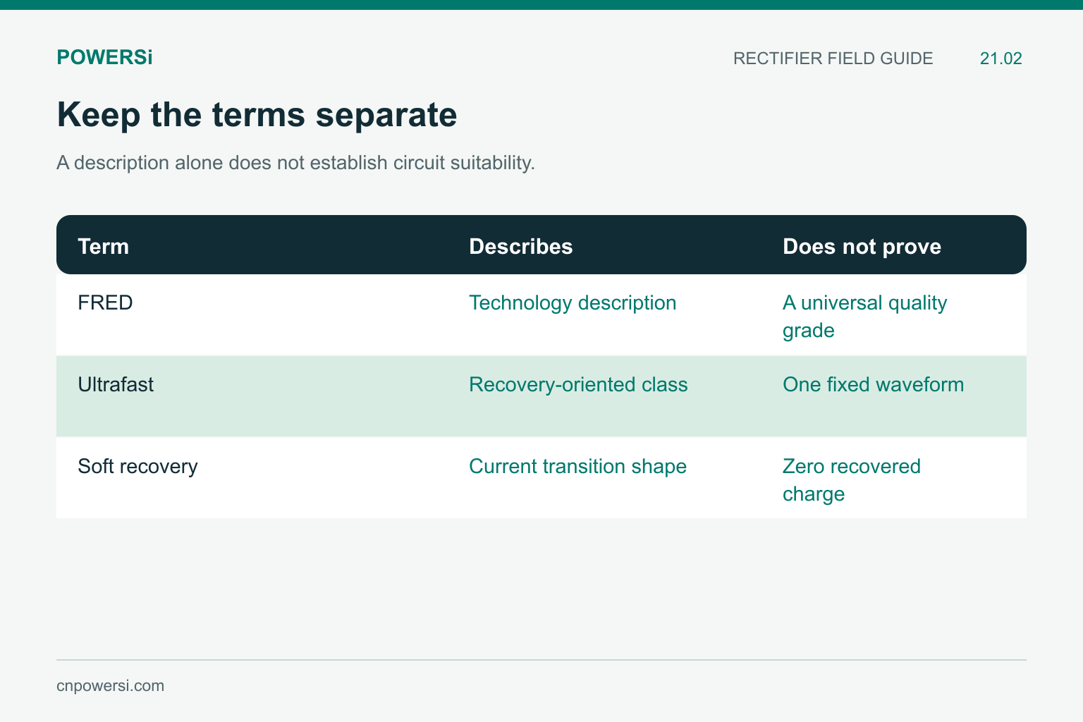
A description alone does not establish circuit suitability.
Do Not Treat the Labels as Separate Grades
FRED means fast recovery epitaxial diode, as used in Littelfuse’s FRED application note. Ultrafast describes a recovery-oriented product class. A FRED can also be described as ultrafast; the terms do not establish two mutually exclusive construction or performance groups.
Soft recovery describes the shape of the reverse-current transition toward zero. It does not mean zero recovered charge, and a shorter recovery-time entry does not necessarily mean a smoother transition. Compare the complete waveform and its conditions. Do not infer an exact wafer process from a family folder, package appearance or the word “soft.”
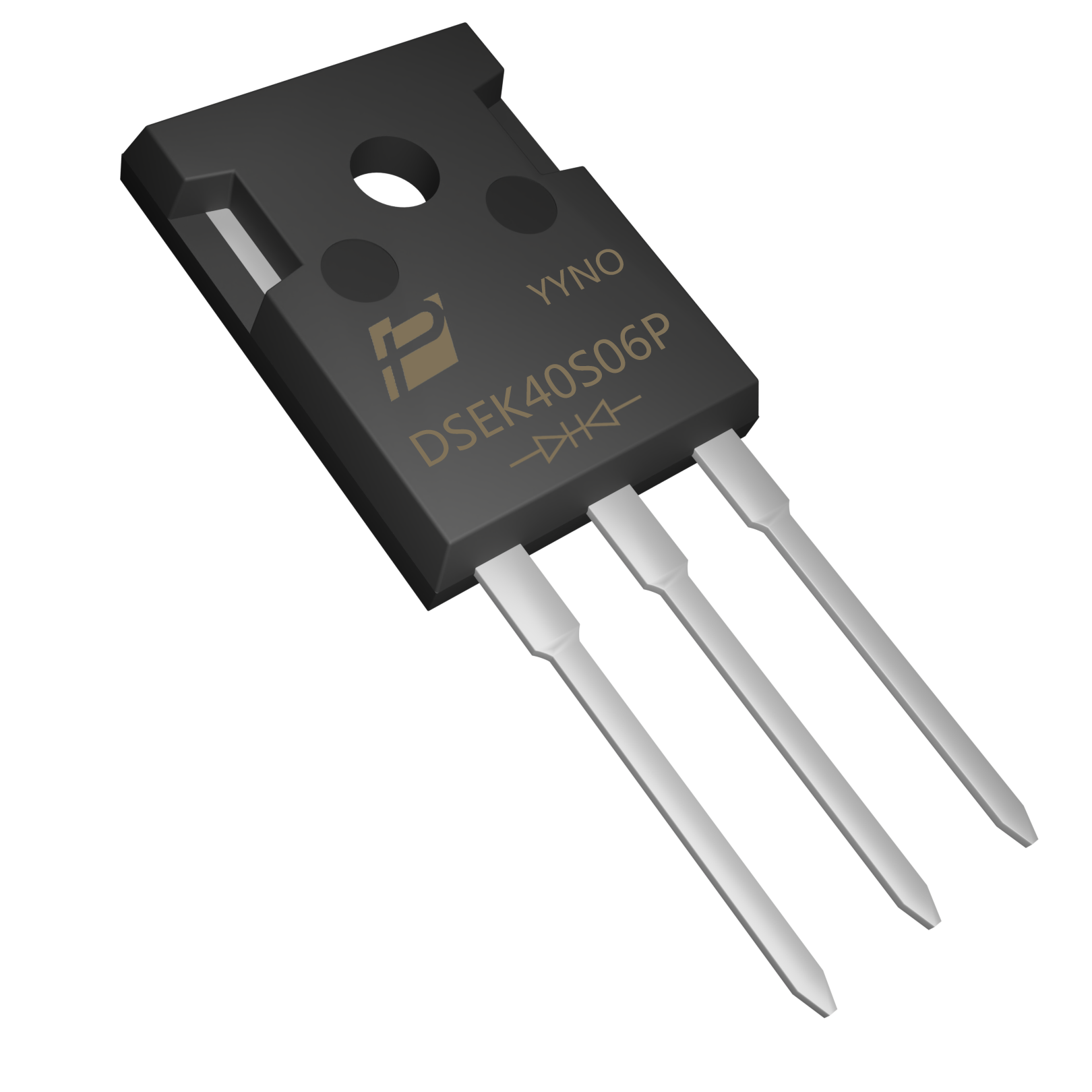
DSEK40S06P original model image; its 35 ns maximum entry applies to the specified low-current recovery test.
Use a Product Entry Without Overextending It
POWERSi identifies DSEK40S06P V2.0 as an Ultra Soft Recovery Rectifier. Its electrical table lists a maximum reverse recovery time of 35 ns at Tj = 25°C, IF = 0.5 A, IR = 1 A and Irr = 0.25 A. That is a conditioned timing entry, not a measurement at every converter load.
The same document distinguishes 40 A per device from 20 A per diode. Keep that scope intact when setting a test current. Neither the package-total current nor the 35 ns result alone establishes a permissible switching frequency or a guaranteed reduction in electromagnetic interference.
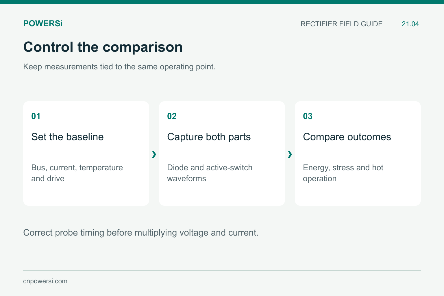
Correct probe timing before multiplying voltage and current.
Build a Controlled Candidate Comparison
Begin with the existing circuit and change one candidate at a time. Keep bus voltage, current before commutation, temperature, gate-drive settings, cooling and measurement placement consistent. If mounting or connection changes are unavoidable, record them because they can change the parasitic circuit.
| Record | Purpose |
|---|---|
| Diode current and reverse voltage | Identify charge, recovery shape and voltage stress |
| Switch voltage and current | Calculate turn-on energy over a defined interval |
| Forward drop and conduction duty | Estimate the conduction-loss contribution |
| Hot steady operation | Check whether the thermal result remains acceptable |
Use probes with suitable bandwidth and ratings. Align voltage and current timing before multiplying traces; probe delay can distort an energy calculation. Repeat measurements at the application’s relevant current and temperature extremes, not just a convenient room-temperature point.
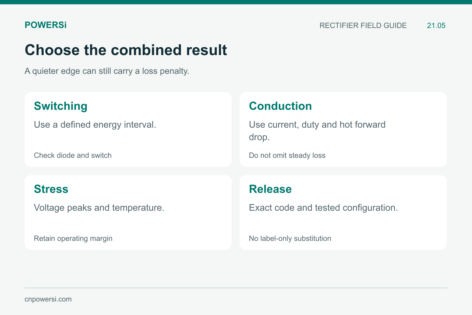
A quieter edge can still carry a loss penalty.
Decide on the Combined Result
Assess switching energy together with conduction and reverse-blocking losses. Then consider component temperatures, repetitive peak voltages and emissions. The preferred device is the one that satisfies these constraints in the intended assembly, with an acceptable procurement and mechanical fit.
A slower switching edge or snubber can change the comparison. Evaluate the extra dissipation rather than counting a cleaner waveform as a free improvement. When a candidate is approved, retain the exact ordering code and the tested gate-drive and layout configuration. An approval for one part is not permission to substitute any product carrying the same technology label.
Key Takeaways
- FRED and ultrafast descriptions can overlap.
- Keep recovery-time conditions and current scope with the number.
- Compare diode behavior and switch turn-on energy together.
- Release the exact candidate against electrical, thermal and emissions targets.
Conclusion
Choose a diode around the switching event that needs improvement. When discussing POWERSi rectifier candidates, provide the circuit position, commutation waveforms, temperature range and acceptance targets so that the comparison addresses the real operating duty.
FAQs
Is a FRED always better than an ultrafast diode?
No. The descriptions overlap, and the relative result depends on the exact devices and circuit conditions.
Does soft recovery mean no reverse recovery current?
No. It describes the transition shape, not the absence of stored-charge recovery.
Can I convert 35 ns into a maximum switching frequency?
No. A timing entry alone does not establish allowable switching loss, temperature or circuit stress.
Why measure the active switch when changing the diode?
Diode commutation can affect switch current and turn-on energy, so the loss change may appear in both components.
Which settings should stay fixed during the first comparison?
Keep the bus voltage, initial current, temperature, drive settings, cooling and measurement arrangement consistent.


