 Skip to content
KBPC, GBJ and GBU Bridge Rectifiers: Choose the Mounting Interface First
Last Updated: 2026-09-26
Quick Answer
KBPC, GBJ and GBU bridge rectifier packages differ in their mounting and connection arrangements, but the family name alone does not establish interchangeability or usable current. Compare the exact outline, terminal map, installed envelope and thermal conditions. Choose a package that fits the assembly before comparing electrical candidates within that interface.
A bridge can meet the voltage requirement and still be unsuitable because its terminals miss the board holes, its mounting point conflicts with the enclosure, or its cooling arrangement differs from the test condition. Package selection should begin at those interfaces.
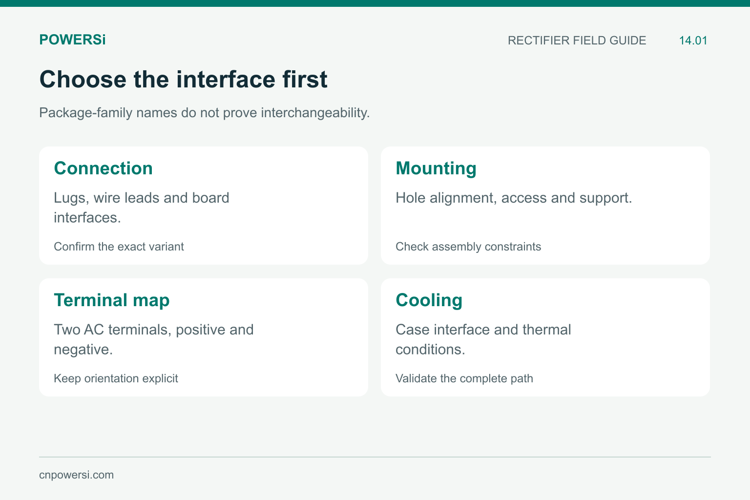
Mechanical and electrical approval are both necessary.
Compare the Connection Method
POWERSi’s KBPC25-series document distinguishes a metal-case version with Faston lugs from a KBPC-W version with wire leads. The W option changes the external connection style within that documented series. It should not be treated as an interchangeable shipping option.
GBJ and GBU examples use molded bodies with four leads arranged along one edge. That broad resemblance does not prove the same lead spacing, terminal order or mounting geometry. A generic four-hole footprint is not an adequate package definition.
| Family example | Interface to establish | Practical decision |
|---|---|---|
| KBPC25 | Lug or wire-lead option | Connector or board assembly method |
| GBJ2510 | Exact lead form and mounting outline | Board clearance and heatsink alignment |
| GBU2510 | Exact lead form and mounting outline | Installed envelope and insertion fit |
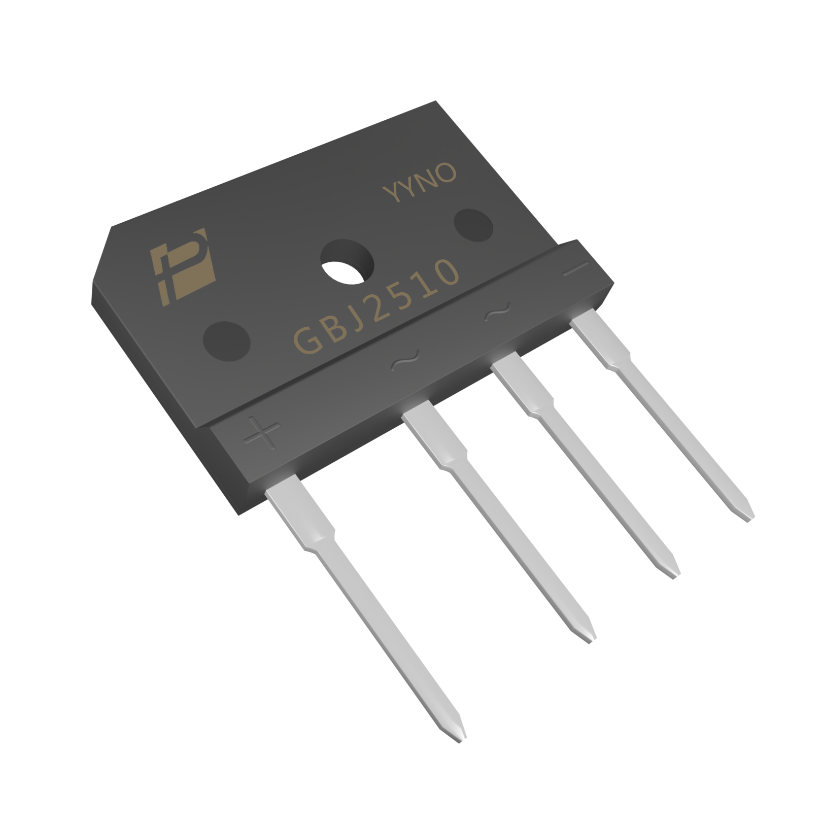
GBJ2510 original model reference with four leads and its actual mounting-hole geometry.
Use Real Model Geometry
The GBJ2510 and GBU2510 images show different body outlines and mounting-hole shapes. Preserve the actual model drawing when building the assembly. A photograph can help recognize a part, but it cannot establish a tolerance, scale or controlled pin assignment.
The relevant POWERSi V2.0 drawings also show multiple lead-form options. GBJ2510 includes standard, C40 and D35 outlines; GBU2510 includes standard and C40 outlines. This means even a correct base model name needs the approved mechanical option. Dimensions should come from the specified drawing revision, including minimum and maximum values.
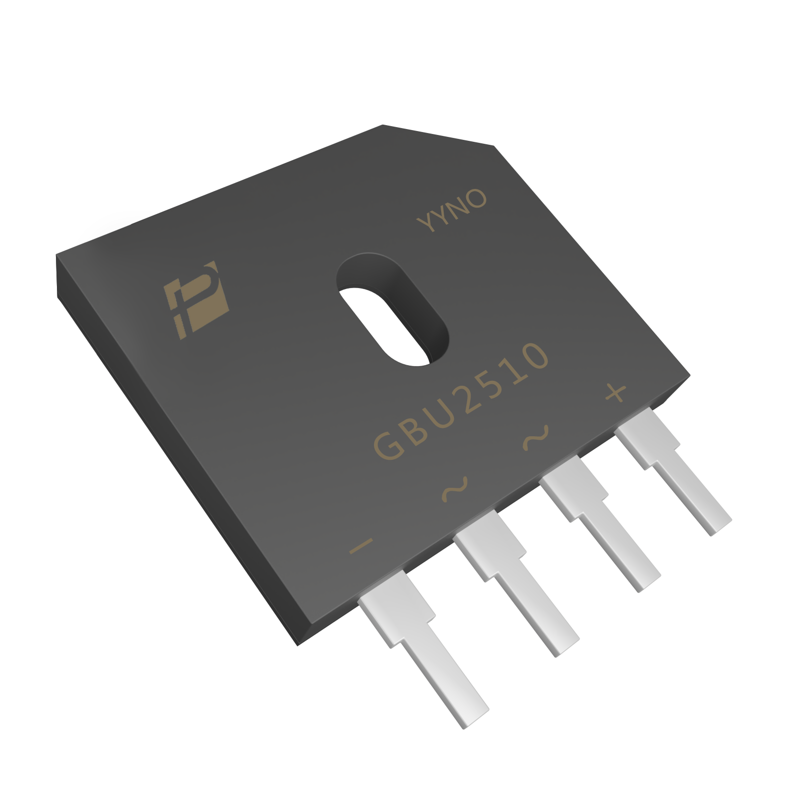
GBU2510 original model reference with four leads; do not infer interchangeability from appearance.
Map Four Terminals Without Assuming Their Order
A bridge has two AC connections and positive and negative DC connections. Their physical order must come from the exact model’s terminal identification. Carry that mapping into the schematic symbol, footprint and assembly inspection record.
Do not identify polarity by counting pins from a photo taken at an unknown orientation. Establish the viewing direction, pin references and installed orientation together. Cable assemblies also need a defined connector-to-terminal map so that a mechanically compatible replacement cannot silently reverse the DC output.
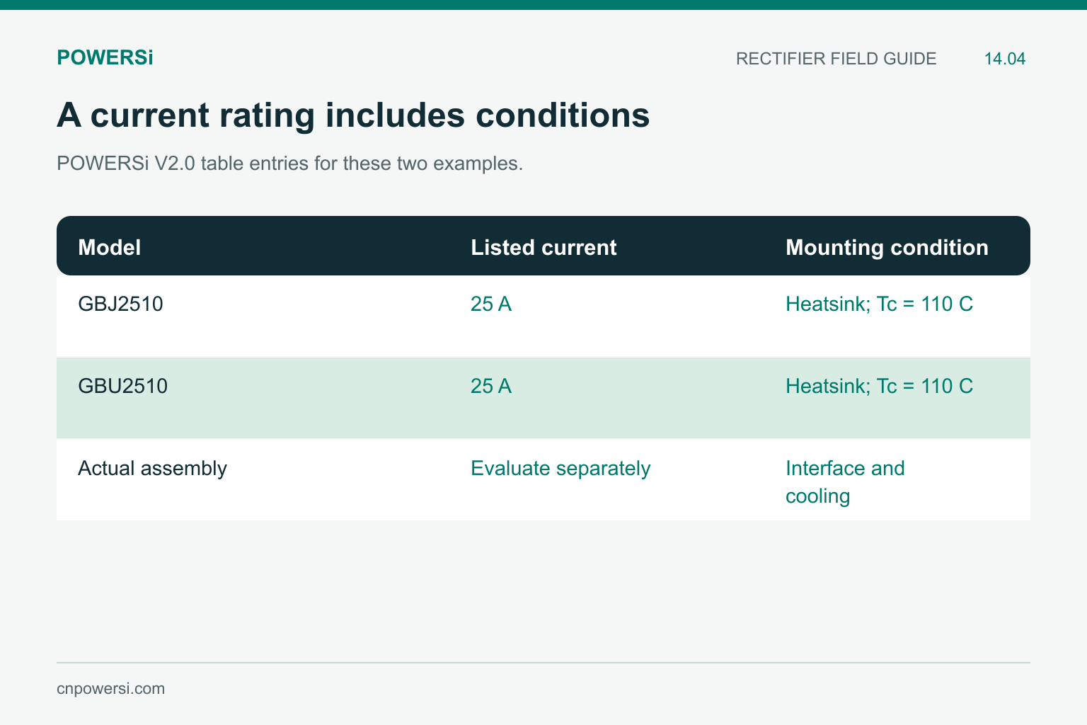
Equal listed current does not establish equal behavior in every assembly.
Compare Ratings Under Their Mounting Conditions
Both the POWERSi GBJ2510 and GBU2510 V2.0 tables list 25 A with a heatsink at Tc = 110°C. Equal headline current does not establish equal thermal behavior on an arbitrary board. Each assembly has its own interface resistance, heatsink temperature and airflow.
For package screening, determine how heat reaches the heatsink and whether the mounting hardware is accessible. Check the applicable torque, insulation requirement and mechanical support using the selected product’s limits. Do not transfer a torque value from one package family to another. Over-tightening is not a substitute for a correctly designed thermal interface.
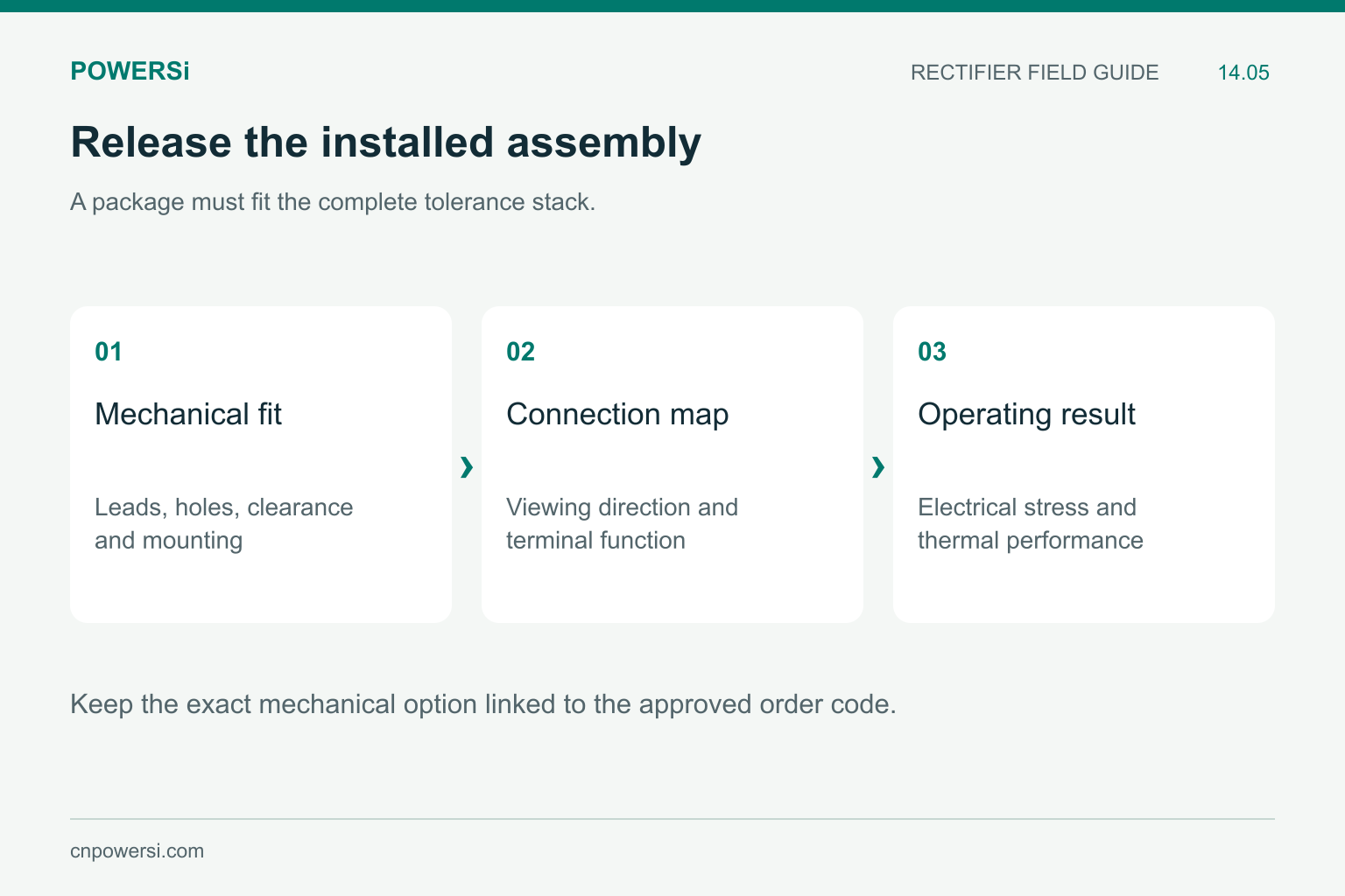
A sample fit complements a controlled dimensional comparison.
Run a Mechanical Release Before a Supplier Change
Compare the candidate against the actual board, connector and enclosure tolerances. Confirm terminal dimensions, formed lead pitch, installed height, body clearance and mounting alignment. Use samples to verify insertion or connector engagement and the production process, not just a visual resemblance at the purchasing desk.
Electrical release remains separate: compare reverse voltage, current conditions, surge capability and thermal performance. A mechanical match is necessary for a straightforward substitution, but it is not sufficient to establish electrical equivalence.
Key Takeaways
- Select the connection and mounting interface before the headline rating.
- KBPC lug and wire-lead variants need distinct assembly treatment.
- GBJ and GBU names do not define a universal shared footprint.
- Carry terminal orientation and mechanical options into the BOM.
Conclusion
A bridge-package comparison is complete when the part fits the circuit and the assembly under controlled conditions. Send the exact order code, board or connector interface, mounting constraints and thermal requirement when discussing POWERSi bridge options.
FAQs
Are GBJ and GBU drop-in replacements?
Not by family name alone. Compare their exact dimensions, terminal mapping, lead options and thermal conditions.
What does W mean in the cited KBPC25 series?
The POWERSi document uses W for the wire-lead version, in contrast to the version with Faston lugs.
Is the largest package always the coolest?
No. Die losses, internal heat paths, mounting interfaces and external cooling determine the operating temperature.
Can a product image define the footprint?
No. Use a controlled dimensional drawing with tolerances and a defined terminal orientation.
What should procurement keep for a package alternate?
Keep the full code, outline revision, terminal map, mounting requirements and both mechanical and electrical approval results.


