 Skip to content
Rectifier diode selection starts with reverse voltage, current, forward voltage and switching behavior. Match VRRM, IF, VF and trr to the actual circuit, retaining their test conditions. Then account for temperature, package and connections. A matching voltage and current headline alone does not establish a suitable replacement.
Why can two rectifier diodes marked “600 V, 30 A” produce different power-supply temperatures and efficiencies?
Voltage and current ratings describe only part of their performance. Forward voltage affects conduction loss, reverse recovery affects switching, and the package and cooling arrangement affect operation at temperature. For buyers and engineers, rectifier diode selection starts by connecting these parameters to the conditions in the circuit.
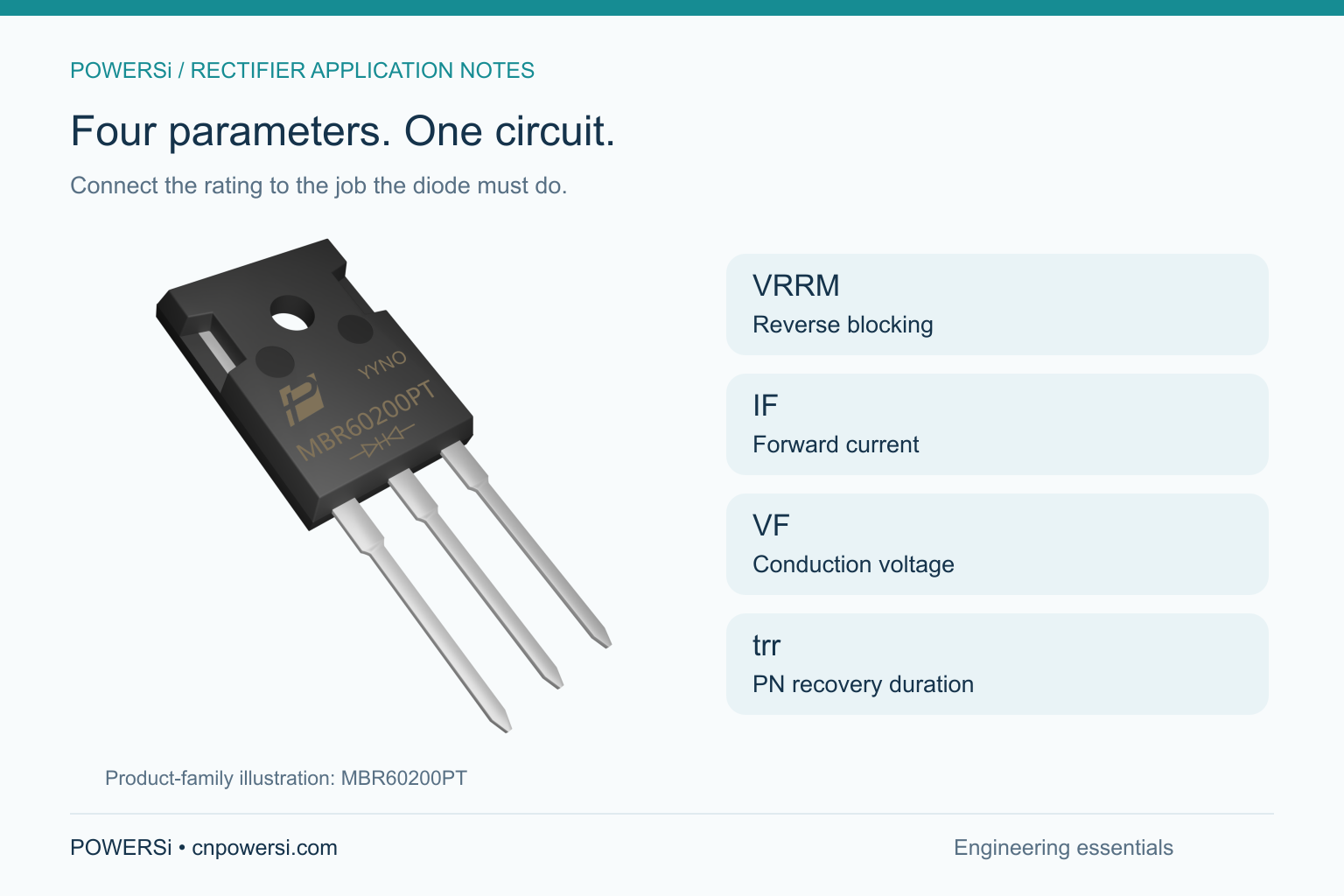
Four Parameters, Four Questions
| Parameter | Meaning | Selection question |
|---|---|---|
| VRRM | Repetitive peak reverse voltage | What recurring reverse-voltage peak can the diode withstand? |
| IF | Forward current; IF(AV) commonly specifies an average rating | Is the stated current an average, a peak or a test current? |
| VF | Forward voltage drop | What voltage appears across the conducting diode at the specified current and temperature? |
| trr | Reverse recovery time | How long does recovery take when the diode changes from forward conduction to reverse blocking? |
1. VRRM: Look at the Reverse Voltage Across the Diode
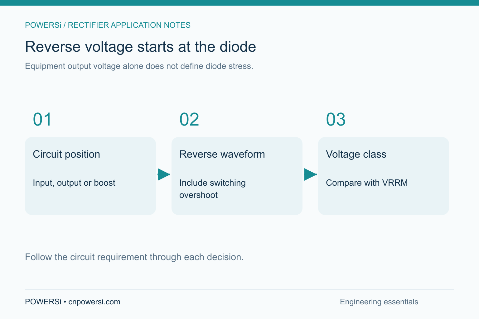
Compare VRRM with the reverse voltage the diode experiences, rather than directly with the equipment's output voltage.
Diodes in input rectifiers, transformer-secondary rectifiers and boost circuits experience different blocking conditions. Switching overshoot can add to that voltage stress.
A quotation request that says only “for a 48 V power supply” therefore leaves an important selection input open. Adding the diode's circuit position and maximum reverse voltage helps the supplier identify the appropriate voltage class.
2. IF: Separate Average, Peak and Surge Current
“30 A” on a purchasing sheet should refer to a specific parameter and operating condition.
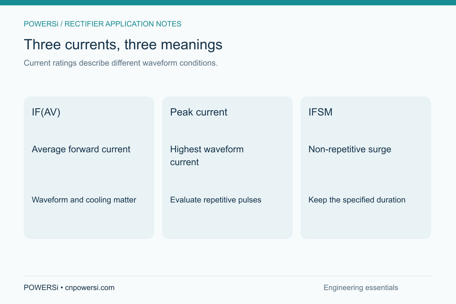
IF(AV) is average forward current. Its rating is associated with specified waveform, mounting and temperature conditions. Two parts with the same current rating can show different temperatures in equipment with different cooling arrangements.
Peak current is the highest current in the waveform. During pulsed conduction, it can be substantially higher than the average. Meeting the average-current requirement does not establish that the peak-current requirement is met.
IFSM is non-repetitive forward surge current. It describes a short surge under specified waveform and duration conditions; it is not the normal operating-current rating.
For dual-diode devices, also distinguish a device-level rating from a per-diode rating. Recording this distinction reduces ambiguity in part comparisons and replacement assessments.
3. VF: Match the Test Conditions Before Comparing
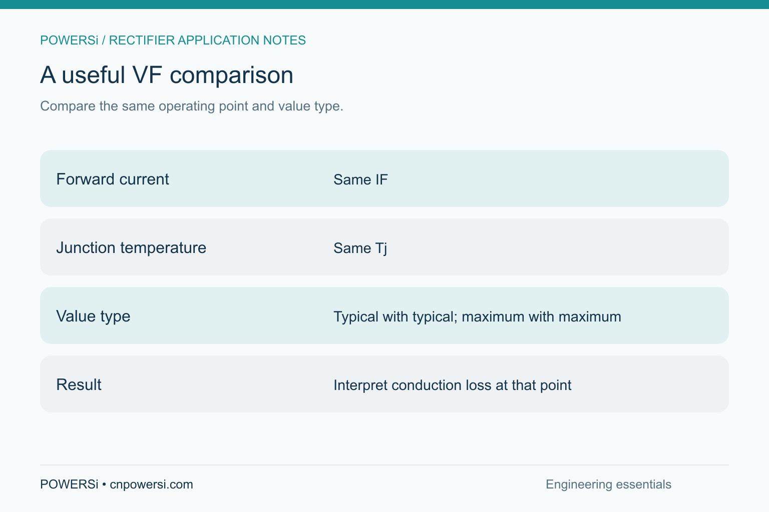
A lower forward voltage generally reduces conduction loss at the same conducting current. Direct comparisons require matching current, junction temperature and value type.
For example, a typical voltage specified at low current cannot be ranked directly against another device's maximum voltage specified at high current. The smaller number alone does not establish lower loss in the intended application.
A useful purchasing comparison records VF as “value + IF + Tj + typical/maximum.” This gives engineers more information than a voltage number by itself.
For Schottky devices, include reverse leakage and its temperature dependence. Lower forward drop does not automatically mean the lowest total loss over a complete operating cycle.
4. trr: Switching Selection Goes Beyond Speed
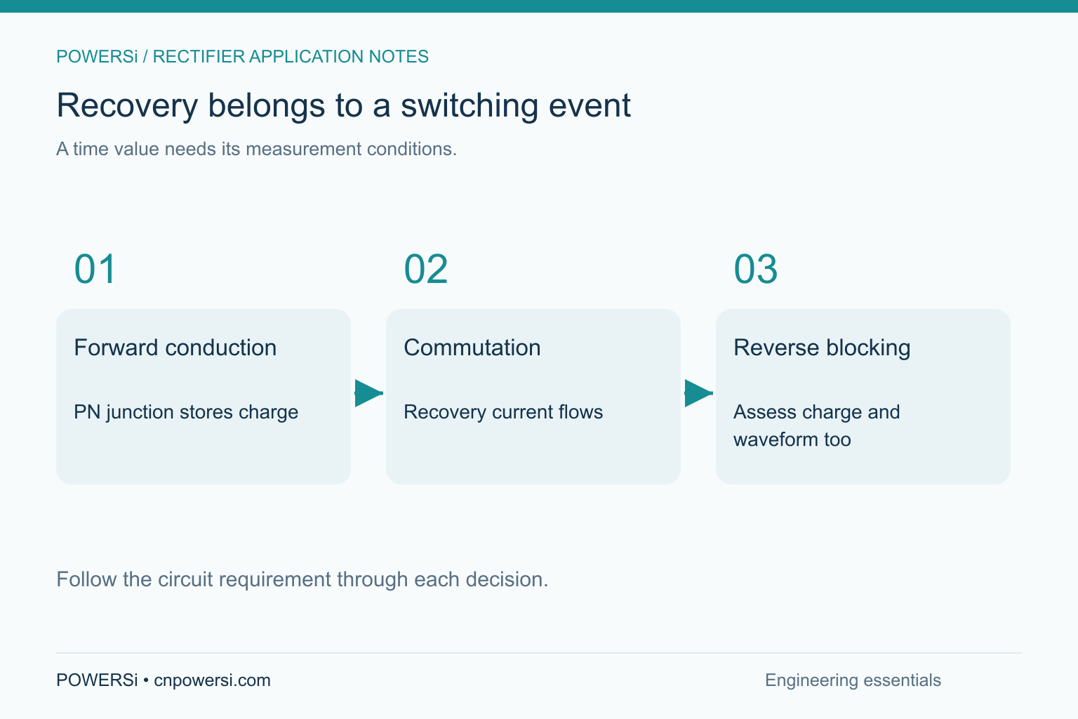
A PN-junction rectifier undergoes reverse recovery when it changes from forward conduction to reverse blocking. The trr value describes the duration of that recovery and is an important parameter when comparing fast and ultrafast devices.
Recovery time also depends on the test conditions. Different currents, reverse conditions and measurement criteria can produce different results.
In a high-frequency circuit, assess recovery charge, waveform and actual switching conditions as well. The objective is to meet the design's loss and electrical-stress requirements, rather than simply select the smallest trr number.
Schottky and PN-junction diodes have different switching mechanisms. Compare the dynamic parameters appropriate to each device type instead of applying a single trr ranking to every rectifier.
Turn the Parameters Into a Clear Purchasing Request
Alongside quantity and requested delivery date, include:
- Circuit role: input rectification, secondary rectification, freewheeling or another position.
- Voltage and current: maximum reverse voltage, average current and peak current.
- Operating conditions: switching frequency, temperature range and cooling arrangement.
- Assembly requirements: package, lead arrangement, polarity and dimensional limits.
- Replacement requirements: original part number, characteristics to retain and engineering validation requirements.
These details help the supplier narrow the candidate list and keep the quotation and engineering assessment focused on the same requirements.
POWERSi offers bridge rectifiers, fast and ultrafast recovery rectifiers, Schottky rectifiers and silicon carbide Schottky rectifiers. For selection information or samples, visit the POWERSi product catalog or send your existing part number or circuit requirements to [email protected].
FAQs
Can parts with the same voltage and current ratings be directly substituted?
Compare recovery behavior, forward voltage, leakage, thermal characteristics, package and lead connections as well. Matching voltage and current establishes only part of the comparison.
Does a lower VF always improve equipment efficiency?
No. Switching loss, reverse leakage and losses in other components also contribute. Compare performance under the intended operating conditions.
Is trr a priority for every diode?
Different device types and applications have different dynamic requirements. High-frequency applications require close attention to switching behavior; one parameter cannot serve as a universal ranking for all rectifiers.
Why does engineering also review the package?
The package affects connections, available space and the heat path. Electrically similar parts may still require different mounting or wiring.
Can I request selection support without complete design parameters?
Start with the original part number, circuit role and known operating conditions. Identify the available information and remaining inputs, then narrow the candidates as the design becomes clearer.


