Skip to content

Last Updated: November 5, 2026
Key Engineering Takeaways
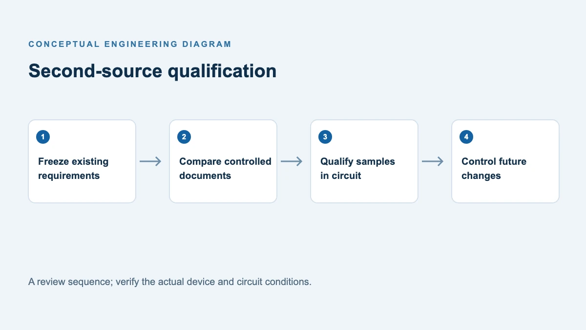
- Record exact ordering codes, configurations and source-document revisions before comparing alternatives.
- Resolve differing surge definitions with the supplier and verify the actual circuit stresses.
- Release a second source only under the equipment owner’s qualification and change controls.
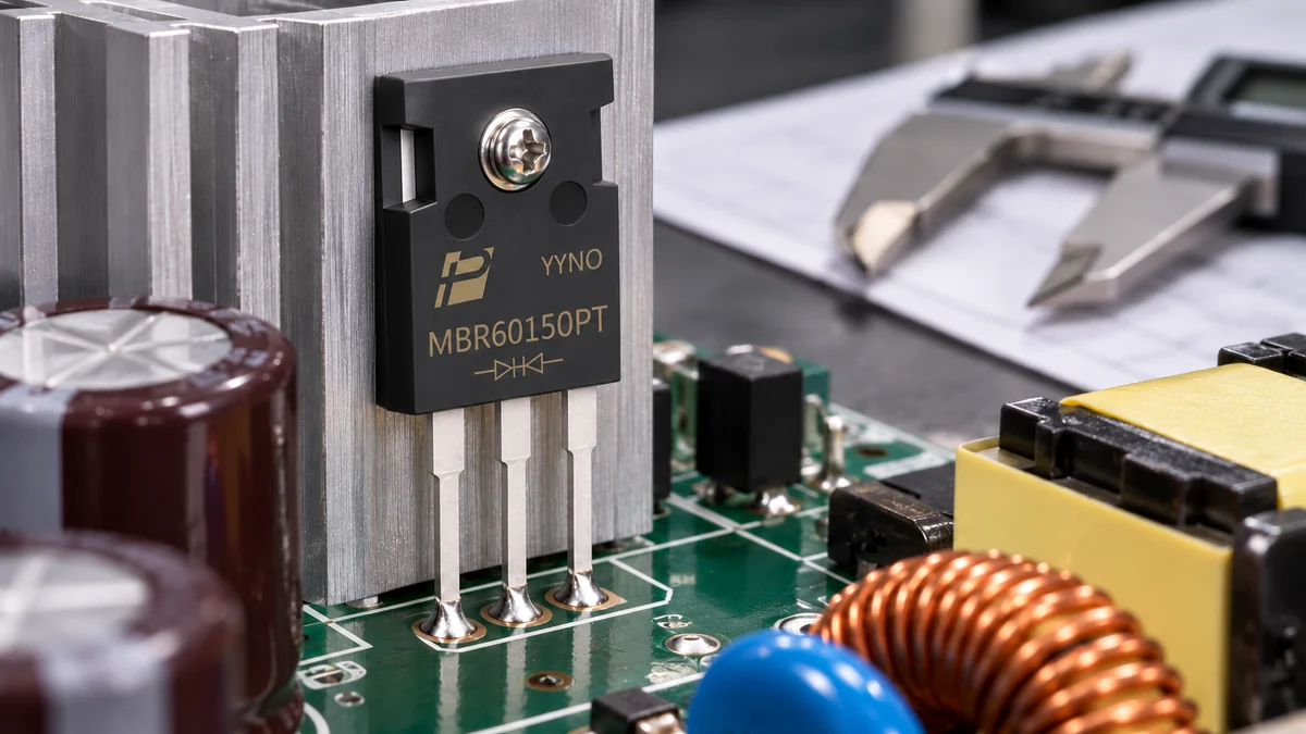
Quick answer: Matching an MBR60150PT marking is only the beginning. Freeze the exact order codes and document revisions, resolve conflicting specifications with the supplier, compare ratings at matching conditions, then test the candidate in the actual circuit and assembly. Release an alternate only after engineering, quality and purchasing have documented approval and change controls.
Establish the controlled specification before comparison
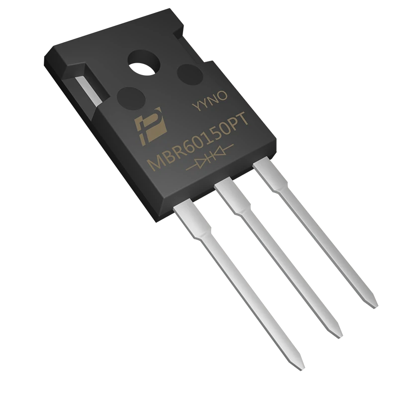
The POWERSi MBR60150PT datasheet, marked “VER: 2.0 10-24,” and the POWERSi product page should be recorded as separate source documents; neither public copy should be assumed to be the controlled specification for a particular order without manufacturer confirmation. In an earlier comparison of available versions, the PDF listed 400 A non-repetitive forward surge at an 8.3 ms single pulse without specifying per-leg or package basis, while the page displayed 300 A per diode for an 8.3 ms non-repetitive pulse. The basis is therefore not directly comparable. The page and PDF also list different maximum forward voltages at 30 A and 25 °C (0.95 V and 0.92 V, respectively) and junction-to-case thermal resistances (1.0 and 1.2 °C/W, respectively). Pages may change, and conditions or revisions may explain a discrepancy: capture both current documents, compare the full conditions and thermal definitions, and request a signed or traceable written clarification before choosing an acceptance limit. Do not silently choose whichever figure is higher.
A datasheet describes a family or part; it does not approve a substitute in your design. Even a different manufacturer using the same part number may specify current, surge or package dimensions under different conditions. Conversely, another part number may meet a given requirement after full evaluation. This is a qualification decision, not an automatic cross-reference.
Gate 1: identify the exact item
Record the manufacturer’s full ordering code, revision, material and plating declarations, lead option, package drawing, marking, lot and date code. The POWERSi PDF lists standard and C40 short-lead variants; compare their dimensions against the mounting fixture and board. Confirm terminal order and whether the tab is electrically connected before applying an insulator or fastening to a shared heatsink. Obtain drawings and any manufacturer change notices for each candidate, not merely a family name.
| Document or attribute | Acceptance question | Evidence to retain |
|---|---|---|
| Orderable part and source | Are full suffix, lead length and manufacturer traceable? | Approved BOM line, purchase description, sample label |
| Electrical configuration | Are pinout, common connection and tab connection compatible? | Manufacturer drawings and continuity check |
| Voltage and current ratings | Do repetitive, surge and temperature limits cover measured stress? | Ratings with waveform and temperature conditions |
| Forward voltage and leakage | Are max/typ values and test conditions aligned? | Original datasheet tables and hot/cold measurements |
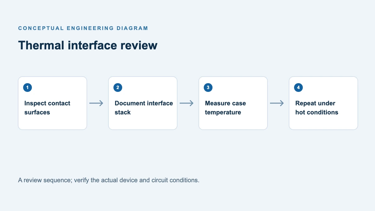
| Mechanical and cooling | Do tolerances, lead length, torque and thermal interface fit? | Drawings, mounting trial, thermal measurements |
| Traceability and change notification | Can lots and process changes be tracked for the agreed scope? | Quality agreement, notification process and sample records |
Gate 2: compare electrical and thermal limits
The PANJIT MBR6040PT series datasheet includes an MBR60150PT; comparing it with POWERSi’s PDF shows why retaining test conditions matters. For example, a current limit defined under a specified case temperature and waveform is not interchangeable with a number whose case temperature is unspecified. Compare total-device and per-diode ratings separately. Compare leakage at equal reverse voltage and junction temperature, and treat typical values as typical, not guaranteed maxima.
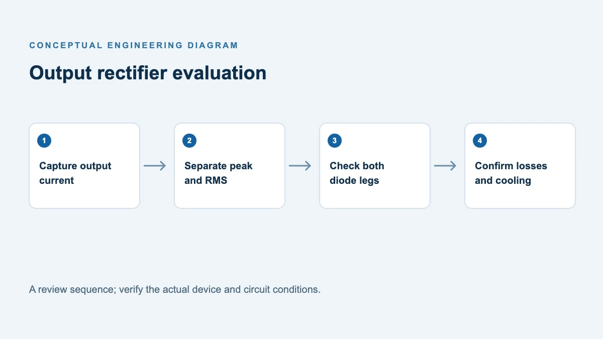
For the actual converter, measure worst repetitive reverse voltage including overshoot, diode current waveform, startup/inrush and overload. Use waveform-based estimates of conduction and reverse leakage loss and the thermal path from each junction to case and heatsink. A dual common-cathode device can have thermal coupling between its two legs; account for both conduction paths. Review startup surge duration and repetition separately from continuous current. If a required parameter or test condition is absent, list it as not established and obtain written clarification or perform an appropriate test.
Gate 3: prove the assembly and circuit
Before making a board substitution, compare lead pitch, body width and height, mounting-hole position, lead length and tolerances using the same drawing reference points. Fit representative samples in the actual PCB and fixture. Confirm insulation, clamping force or torque, heatsink flatness, thermal interface material and clearances against the relevant manufacturer instructions.
Then test the baseline and alternate on equivalent boards at low and high input, light and full load, hot ambient, startup and plausible fault or overload conditions. Capture diode reverse voltage, current, switch waveforms, efficiency and stabilized case temperature. Inspect solder joints and mounting after environmental or cycling tests defined by your qualification plan. Test enough samples and lots for the risk and production volume; a single passing sample shows feasibility, not statistical equivalence.
Gate 4: release and manage change
Create a controlled comparison sheet with source document revision and date, required limit, candidate value and condition, measurement method, result, disposition, and owner. Open deviations when data conflict or a parameter is missing. Before release, close each deviation with a supplier response, revised requirement or approved test evidence.
Engineering signs off on the operating envelope and margins; quality approves traceability and qualification; purchasing confirms the precise approved manufacturer and order code. Define the notification and requalification process for changes to die, assembly site, package, materials or test flow in the supplier agreement. Maintain independent supply-risk information where available; two ordering codes do not by themselves prove independent manufacturing sources.
The related POWERSi article Diode Dual Sourcing: Check Whether Two Suppliers Share the Same Risks focuses on supply dependency. This checklist adds model-specific document-conflict handling, fit and release gates.
A practical discrepancy log and decision trail
For every conflict, record the exact part number and suffix, document title, revision, page or website capture date, parameter, numerical value and its complete test conditions. For the surge example, one entry should state that the PDF lists 400 A for an 8.3 ms single pulse without identifying a per-leg or total-device basis; another should state the webpage’s 300 A per-diode value at 8.3 ms. The open question is whether the documents describe the same configuration, waveform, initial condition and production revision. A supplier response should identify the governing controlled specification for the ordered code and explain the basis; an email that merely repeats a number does not close that question.
Assign an owner and due date to the issue. Until the manufacturer responds or the requirement is otherwise resolved through the approved process, keep the candidate in a pending state. Do not replace a missing guarantee with a typical value or assume the lower of two numbers fully resolves an undefined test basis. If the relevant system requirement is lower than either value, the team still needs to establish that the specified waveform, initial temperature and repetition conditions match the application.
A useful qualification packet includes baseline and alternate documents, the measured mission profile, a pinout and physical-fit check, a comparison matrix, lot identification, bench results, and the disposition of every deviation. For each test, capture the procedure revision, sample count, lot, equipment calibration status, stress conditions, acceptance limits and result. Record failures and retests rather than reporting only the best sample. The equipment owner should set test duration and sample size according to its risk and customer obligations; a generic checklist cannot determine statistical confidence for every program.
Once released, retain the approved manufacturer and exact order code in the controlled BOM. The quality agreement should identify who receives a product-change notice, what information the supplier will provide, and how the team evaluates impact before an affected lot is used. If a die, assembly site or test flow changes, compare the proposed change with the approved evidence and decide whether partial or full requalification is required. Keep the previous release record available for traceability.
Support for your evaluation
For a proposed alternate, provide the application envelope, original order code, relevant drawings and unresolved specification differences when contacting POWERSi. Review the MBR60150PT Schottky rectifier details and request the controlled specification for the exact ordering code.
FAQs
Are two MBR60150PT parts automatically drop-in replacements?
No. Compare the full order code, mechanical tolerances, pinout, ratings, conditions and application behavior, then complete the required approval process.
Which document wins when a page and PDF disagree?
Do not assume. Preserve both versions and ask the manufacturer to confirm the applicable controlled specification and conditions for the exact order code.
Does a passing room-temperature test qualify the alternate?
No. It is one data point. Evaluate the operating envelope, startup, thermal conditions, assembly and any required reliability tests.
Can a distributor add an alternate to the BOM independently?
Follow the equipment owner’s change control and customer approval requirements. An advertised cross-reference is evidence for screening, not an approval.