Skip to content

Last Updated: November 5, 2026
Key Engineering Takeaways
- Recovery softness describes waveform shape; it does not guarantee EMI compliance.
- Verify probe setup and current-loop parasitics before attributing ringing to the diode.
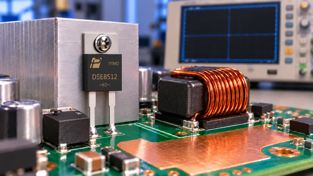
- The DSE8S12 public page and PDF list different recovery, forward-voltage, surge and thermal figures; obtain the controlled revision.
Quick answer: A soft-recovery diode can reduce the abruptness of reverse-current decay in a PN rectifier. This may reduce excitation of circuit parasitics and improve a particular converter’s noise behavior. It does not guarantee EMI compliance: layout, switching speed, damping and the measurement setup remain important.
What “soft” describes
When a conducting PN diode is forced into reverse bias, stored charge produces a reverse current. After the reverse-current peak, the current returns toward zero. Softness refers to the shape of this recovery, particularly the rate at which current decays. A sharp transition can interact with loop inductance and capacitance, generating oscillation and voltage overshoot. Infineon’s introduction to active components discusses why the decay portion of the waveform is relevant to EMI.
The familiar relationship V = L × di/dt explains one contribution to overshoot: a rapid change in current through parasitic inductance generates voltage. A real circuit also contains capacitance, distributed current paths and damping, so this is a diagnostic relationship rather than a complete noise prediction. A fast edge can excite a resonant network even when the diode itself is correctly rated.
Fast and soft answer different questions
| Question | Useful evidence | Why a single number is insufficient |
|---|---|---|
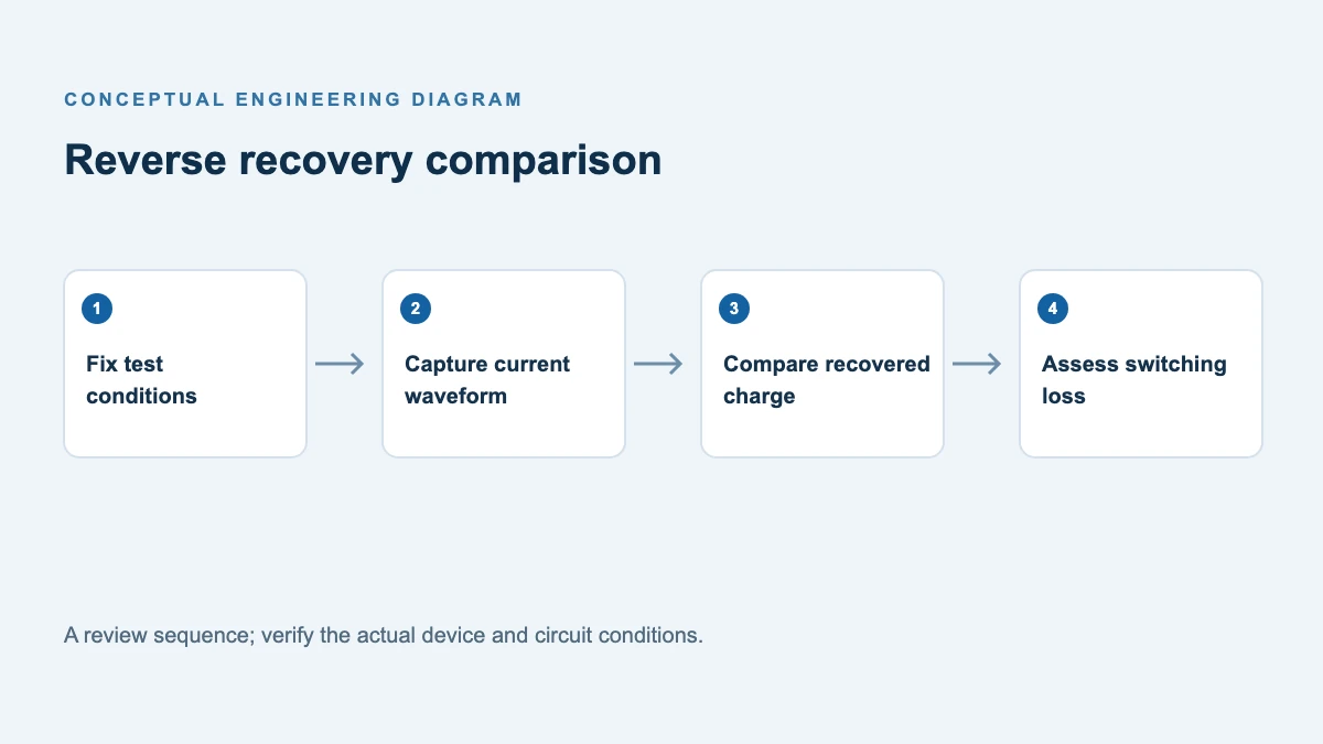
| How long does recovery take? | trr and its test conditions | Time does not uniquely describe peak current or decay shape |
| How much charge is removed? | Qrr at comparable operating conditions | Lower charge does not by itself certify a quieter system |
| How abruptly does current fall? | Recovery waveforms and circuit measurements | Definitions of softness and measurement conditions vary |
| Does it pass EMI? | System-level test against the applicable requirements | Enclosure, cables, filters and switching circuitry all contribute |
A part can be both fast and soft; the terms are not opposites. Conversely, a short trr measured at a low test current should not be interpreted as a guaranteed recovery shape at the application’s current and temperature.
A real device to evaluate
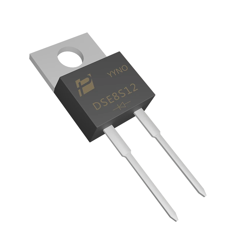
The POWERSi DSE8S12 is listed as an 8 A, 1200 V TO-220AC ultra-soft recovery rectifier. The product page states a 45 ns maximum trr at a defined 0.5 A test condition, whereas its linked version 2.0 datasheet lists 42 ns at the stated 0.5 A forward test current. The webpage and PDF also list different forward-voltage, surge-current and thermal-resistance figures. Request written clarification of the controlled revision and test conditions before using these limits. Neither test point predicts recovery at every application current, temperature or current slope. Verify the device against the actual electrical and thermal stresses.
A 1200 V class component is not automatically suitable for every nominal 1200 V application. Determine the peak repetitive reverse voltage, transients and required engineering margin. Check the peak forward and surge current, cooling, mounting isolation and the exact terminal arrangement before building a prototype. The exposed tab is connected to the cathode; if the heatsink must be at a different potential, use an appropriate insulating mounting interface and account for its thermal resistance, creepage and clearance.
Measure the cause of ringing before changing parts
- Locate the event. Capture diode current, diode reverse voltage, switch voltage and gate signal around the suspected commutation. Check several line, load and temperature points.
- Verify the measurement. Long probe ground leads can add a false ringing loop. Use appropriately rated probes, short connections and a consistent bandwidth for A/B comparisons.
- Inspect current loops. Reduce the area of the high-di/dt loop and place relevant decoupling near the switching path, subject to isolation and thermal constraints.
- Compare candidate devices. Keep the board, switch, gate drive and measurement setup unchanged for the first comparison. Note peak voltage, ringing frequency, decay, current waveform and temperatures.
- Tune the circuit. A gate resistor or appropriately engineered snubber can reduce ringing, but may increase switching or damping loss. Evaluate the trade-off under worst-case conditions.
- Run the applicable EMI test. Near-field probing can locate a source, but it does not replace conducted and radiated compliance testing on the complete product.
If a device swap reduces visible ringing but conducted emissions are unchanged, another coupling path may dominate. If the diode looks quiet at light load but noisy when hot, capture the higher-stress condition rather than extrapolating from room temperature.
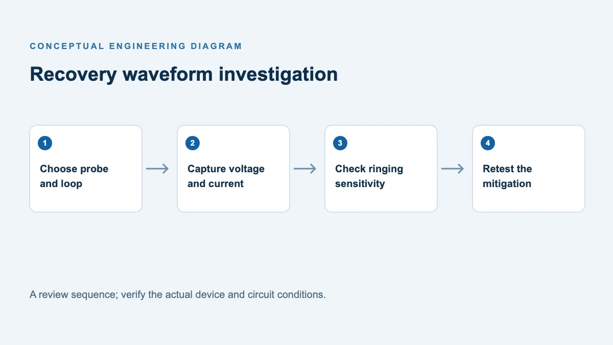
Check whether the probe is creating the ringing
Run a controlled A/B measurement with the same operating point and scope settings. Do not connect an earth-referenced probe ground clip to a floating high-voltage switching node; use a suitably rated differential measurement and follow the instrument and isolation instructions.
| Trial | Change only | Record | Interpretation |
|---|---|---|---|
| A: Baseline | Use a probe rated for the node and specified connection geometry; use a suitable differential or isolated method for a floating high-voltage node | Peak voltage, oscillation frequency, damping, probe position | Reference for later trials |
| B: Shorter connection | Shorten the permitted measurement loop using a manufacturer-approved accessory rated for the node | Same voltage and frequency metrics | A large change suggests measurement-loop contribution; it does not prove all ringing was artificial |
| C: Second method | Use an independently rated differential or isolated method | Bandwidth and observed waveform | Agreement within instrument limits increases confidence |
| D: Layout or damping | Change one circuit element or layout variable after confirming measurement | Voltage, energy, temperature, emissions | Establish the actual circuit trade-off |
The earlier Power Supply EMC Troubleshooting article covers the broader EMC diagnosis. This article adds a controlled probe-layout comparison and measurement record.
Support for your evaluation
Provide the operating waveforms, reverse-voltage peak, current and thermal conditions when contacting POWERSi. Review the DSE8S12 soft-recovery rectifier details and request clarification of the current controlled data sheet.
FAQs
Does soft recovery eliminate a snubber?
Not necessarily. It may reduce the damping needed in some circuits, but the decision requires voltage, loss and EMI measurements across operating conditions.
Is a soft-recovery diode always more efficient?
No. Recovery losses, forward drop and any additional snubber or gate-drive loss must be compared at the system level.
Can an oscilloscope prove EMI compliance?
No. It helps diagnose switching events; compliance depends on the prescribed test method, limits and the complete equipment configuration.
What data should I request when the datasheet has only trr?
Ask for recovery waveforms, test current, reverse voltage, di/dt and temperature, plus Qrr and peak recovery current if available. Verify performance in the target circuit.