 Skip to content
Diode IFSM Explained: Why Rectifiers Can Fail at Startup
Last Updated: 2026-10-07
Quick Answer
Diode IFSM is a non-repetitive forward surge-current rating under specified pulse and temperature conditions. Startup can exceed normal current because an uncharged capacitor initially presents a large voltage difference to the source. Compare the complete inrush waveform and restart conditions with the applicable surge capability, rather than treating IFSM as continuous or freely repeatable current.
A bridge can remain cool at normal load yet fail when power is connected. The load current after startup may be modest, while the first capacitor-charging pulse is much larger. Increasing the average-current rating without examining that pulse can leave the failure mechanism unchanged.
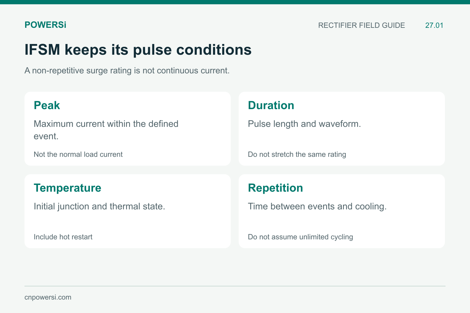
A non-repetitive surge rating is not continuous current.
Read IFSM With Its Conditions
Keep pulse duration, waveform, initial temperature and any reapplied voltage condition with the surge number. An 8.3 ms entry is not permission to carry the same peak for an arbitrary duration. Non-repetitive capability also does not establish an unlimited number of closely spaced restarts.
As an example of why conditions matter, the Vishay VS-8EWF12SLHM3 specification distinguishes surge entries with and without voltage reapplied. This illustrates a rating-definition issue; its values are not replacement criteria for a POWERSi bridge.
POWERSi GBJ2510 V2.0 lists IFSM = 320 A for a non-repetitive single pulse with t = 8.3 ms. Preserve that scope. Do not convert the entry into a repetitive startup allowance or silently add a waveform or hot-temperature guarantee that the entry does not establish.
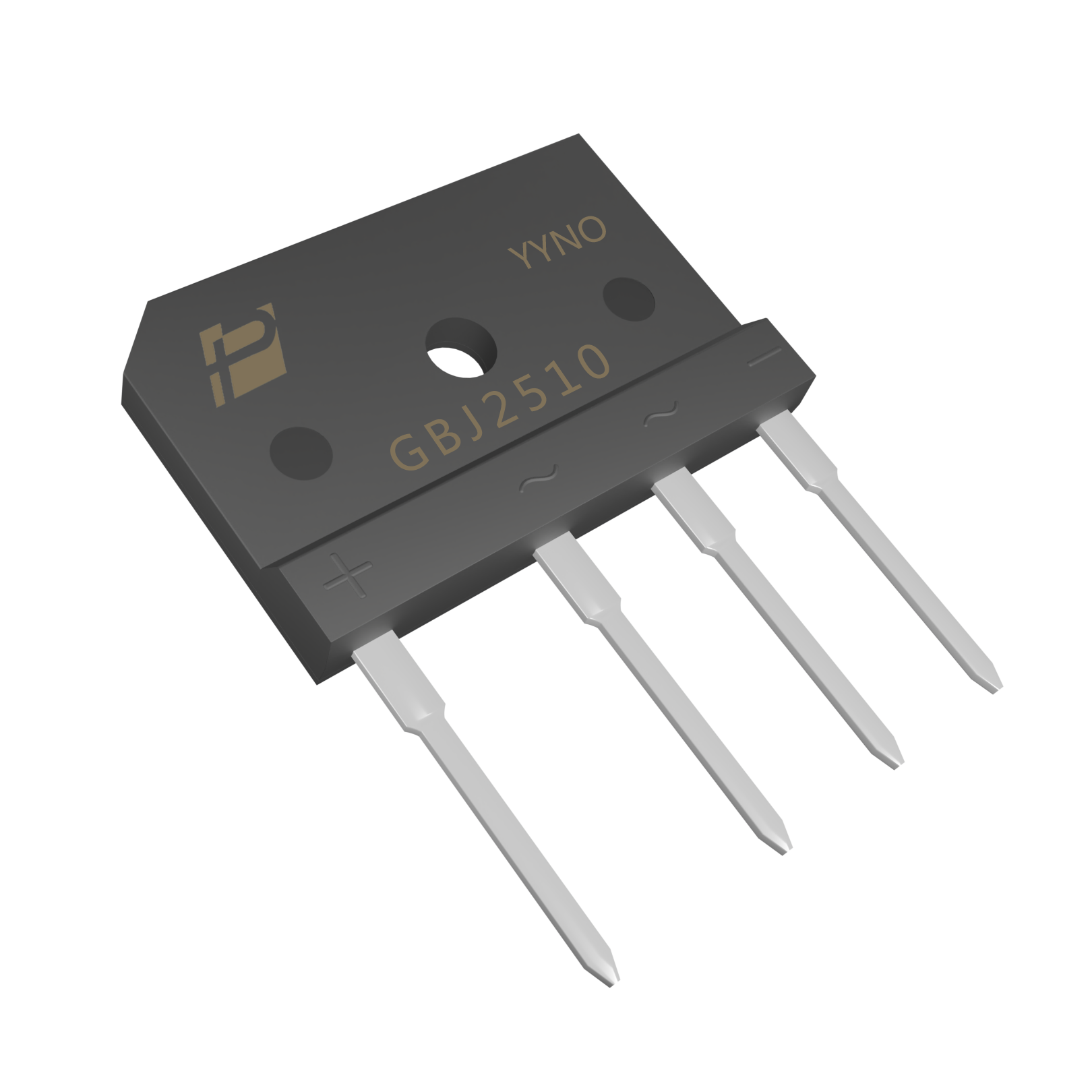
GBJ2510 original model image; IFSM is listed as 320 A for a non-repetitive 8.3 ms single pulse.
Understand the Capacitor-Charging Event
At connection, current is driven by the difference between source voltage and existing capacitor voltage. Source impedance, wiring, rectifier behavior, capacitor ESR and any limiter shape the pulse. For an AC input, switching phase and the capacitor’s remaining charge also matter.
A simplified DC example isolates the principle: a 10 V step charging an initially empty 100 microfarad capacitor through 1 ohm has an initial current of 10 A and an RC time constant of 100 microseconds. This assumes an ideal source and capacitor and neglects diode drop and inductance. It is not a mains-bridge startup model or a GBJ2510 test.
The capacitor stores 0.005 J when charged to 10 V. That stored energy is not the energy dissipated in the rectifier. Diode heating requires the time integral of its own instantaneous voltage multiplied by current.
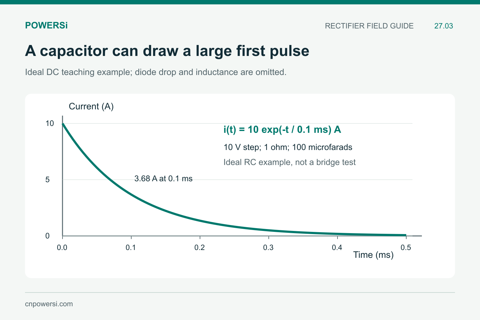
The 0.005 J stored in the capacitor is not the rectifier energy loss.
Compare Pulse Shape, Not Just Peak
Record the measured current versus time. A narrow 100 A pulse and a long 100 A pulse have the same peak but different electrical and thermal effects. The integral of current squared over time, often written I²t, can assist coordination when applicable device and protection specifications provide a valid basis.
I²t is not a universal substitute for peak current, waveform and transient-temperature limits. Do not derive an unrestricted surge curve from one IFSM entry. Fuse coordination also needs the fuse’s relevant clearing behavior and the operating voltage, rather than only a comparison of nominal amperes.
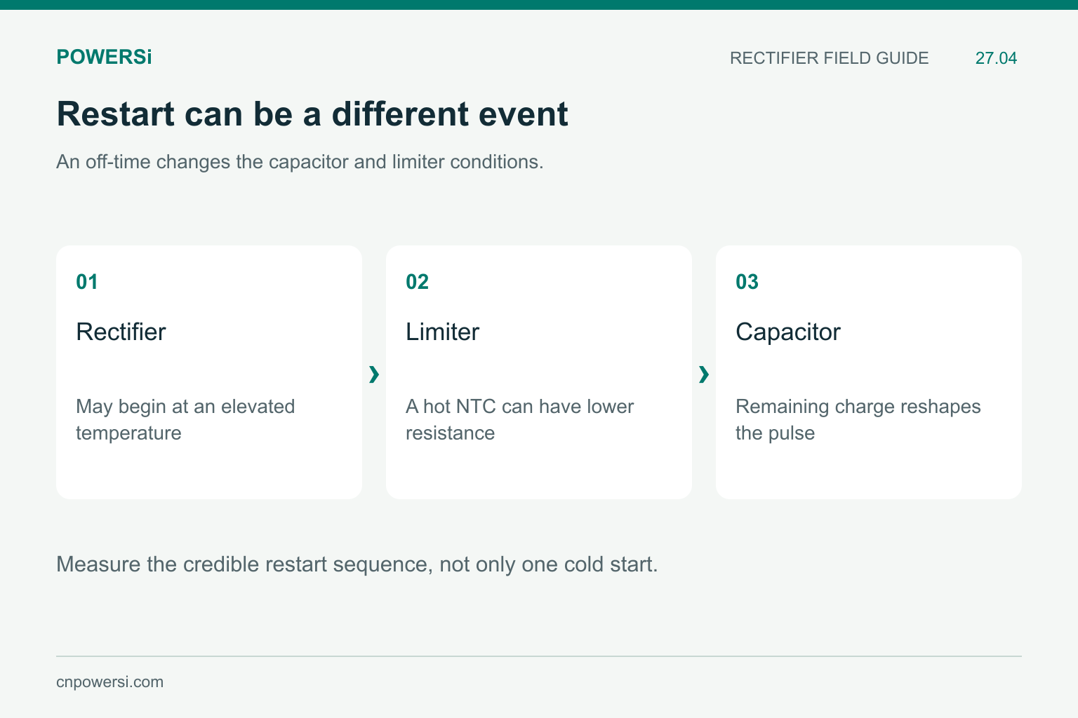
Measure the credible restart sequence, not only one cold start.
Include Hot Restart and Repetition
Test a cold start and the credible restart sequence. A rectifier can begin a second pulse at an elevated junction temperature. An NTC limiter may also remain hot and provide less resistance than it did at the first start. Residual capacitor charge can reduce or reshape inrush, so the worst case is not necessarily the longest or shortest off-time.
Define the source voltage range, source impedance, capacitor tolerance, off-time and initial thermal condition. Use those conditions to evaluate the complete assembly. A successful isolated bench pulse does not prove that rapid cycling or every installation source is acceptable.
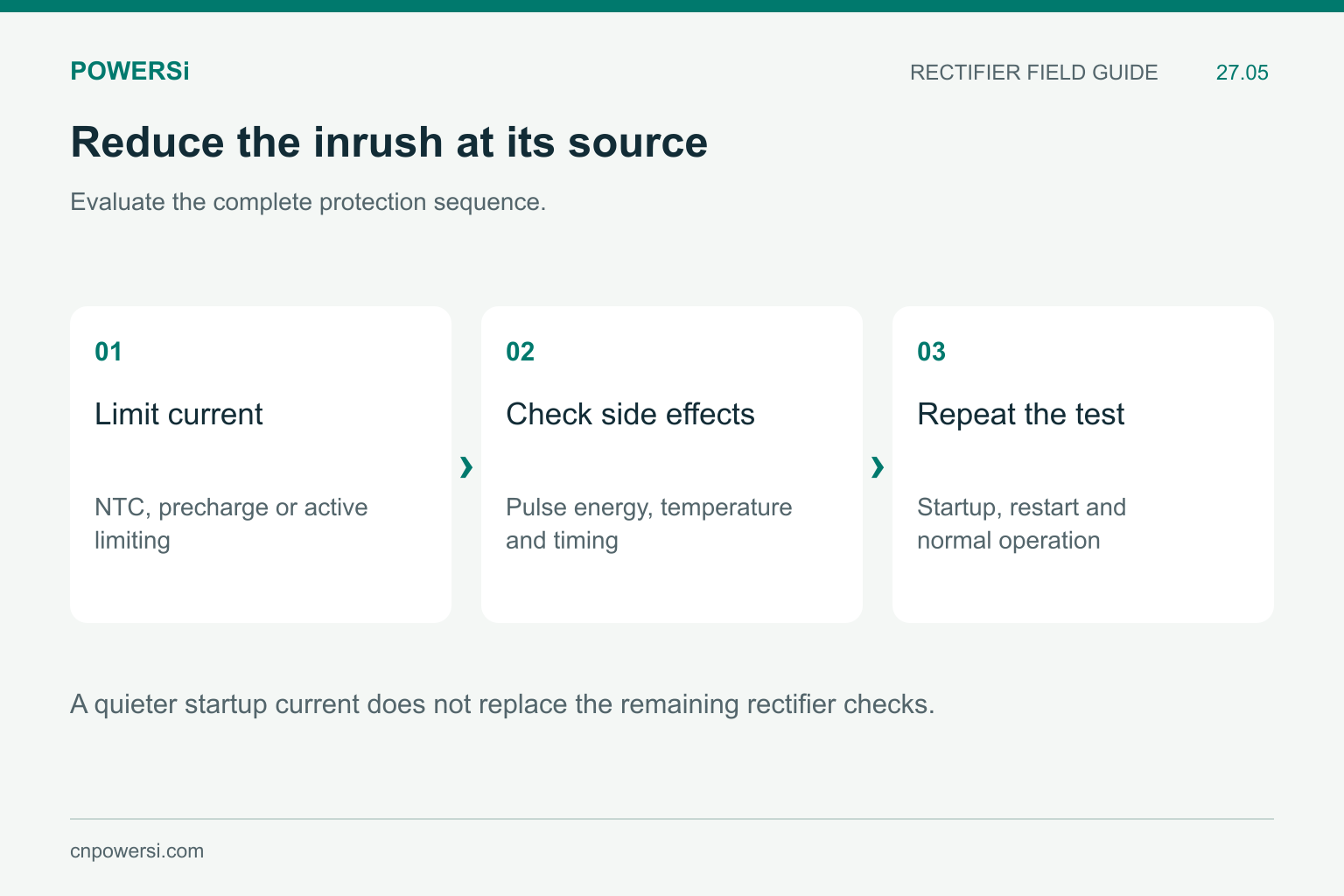
A quieter startup current does not replace the remaining rectifier checks.
Reduce the Stress at Its Source
Possible measures include a suitable inrush limiter, a controlled precharge path or active current limiting. Each introduces its own requirements: limiter temperature, resistor pulse energy, bypass timing, fault behavior and repeated operation. The appropriate choice depends on the circuit and operating sequence.
After a change, confirm that startup completes correctly and that the protection does not create a new overheating or timing problem. Keep normal-load thermal performance and reverse-voltage margin in the approval as well. Surge capability is one part of rectifier selection, not a replacement for all other ratings.
Key Takeaways
- IFSM is conditional and non-repetitive.
- Capacitor charging can dominate the first current pulse.
- Peak, duration, initial temperature and repetition belong together.
- Include hot restart when evaluating an inrush solution.
Conclusion
Treat startup as a separate operating event. Provide the captured pulse, restart sequence and thermal conditions when selecting a POWERSi bridge rectifier, so that the surge comparison reflects the actual application.
FAQs
Can IFSM be used as a continuous-current rating?
No. It describes a specified non-repetitive surge event.
Does a lower peak always mean a safer pulse?
No. Duration, waveform and initial temperature can change the outcome.
Does capacitor stored energy equal rectifier loss?
No. Rectifier energy loss depends on its own voltage-current history during charging.
Why test an NTC circuit after a short power interruption?
The limiter may still be hot and offer less resistance, changing the restart current.
Does a 320 A, 8.3 ms entry approve repeated 320 A startups?
No. Repetition and the actual thermal and waveform conditions require their own assessment.


