 Skip to content
From Wafer to Finished Rectifier: What Diode Tests Actually Establish
Last Updated: 2026-10-06
Quick Answer
Rectifier diode testing spans wafer-level electrical checks, assembly process controls, finished-device measurements and reliability evaluation. Each stage answers a different question. A passing final electrical test does not prove lifetime reliability, and a qualification sample does not mean every shipped unit received every stress. Buyers need the test conditions, coverage and traceability behind the result.
A certificate stating that a lot passed inspection is useful only when its scope is clear. It may describe final electrical screening, a sampling plan or a process qualification. Asking what was tested, at which stage and on how many units helps distinguish these forms of evidence.
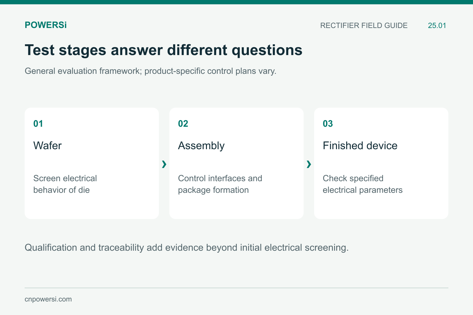
Qualification and traceability add evidence beyond initial electrical screening.
Stage 1: Wafer-Level Electrical Checks
Before assembly, wafer probing can identify die that fail specified electrical criteria. Depending on the device and process, the checks may include forward behavior and reverse leakage or blocking-related measurements. The probe conditions, limits and wafer map link the result to a location on the wafer.
A passing die result does not describe the completed package. Die attach, interconnects, molding and subsequent handling introduce additional interfaces and possible failure mechanisms. Treat wafer screening as one control point rather than proof that all later manufacturing steps are satisfactory.
The sequence described here is a general way to evaluate a rectifier supplier’s evidence. The exact operations and test coverage depend on the product and agreed control plan; they are not a declaration that every POWERSi model undergoes an identical flow.
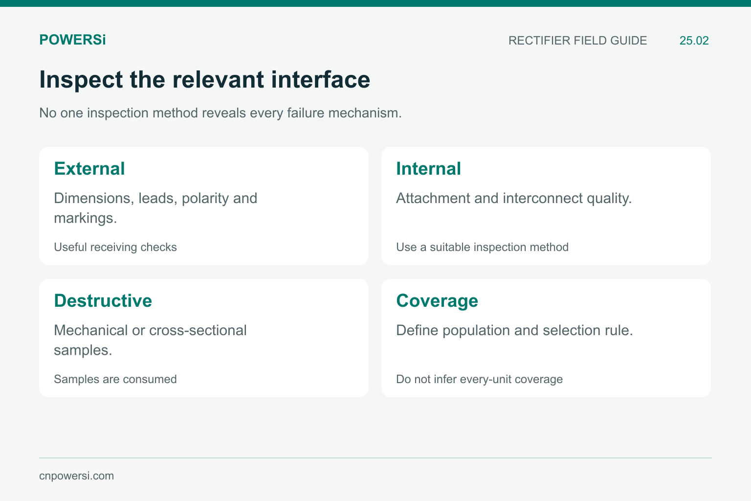
No one inspection method reveals every failure mechanism.
Stage 2: Assembly and Process Controls
Assembly checks address whether the die and package interfaces were formed as intended. Examples can include visual inspection, dimensional checks, interconnect evaluation and process-specific inspection of internal attachment quality. Some methods inspect a sample; others may be applied more broadly under the control plan.
Destructive analysis cannot be performed on every unit intended for shipment. Where destructive mechanical or cross-sectional evaluation is used, keep its sampling basis and acceptance criteria separate from final electrical screening. A photograph of a sound sample does not establish the condition of every unit in a lot.
For procurement, package dimensions, lead condition, marking and polarity are practical receiving checks. However, a normal external appearance cannot reveal every internal attachment problem. Match the inspection method to the failure mechanism it is intended to detect.
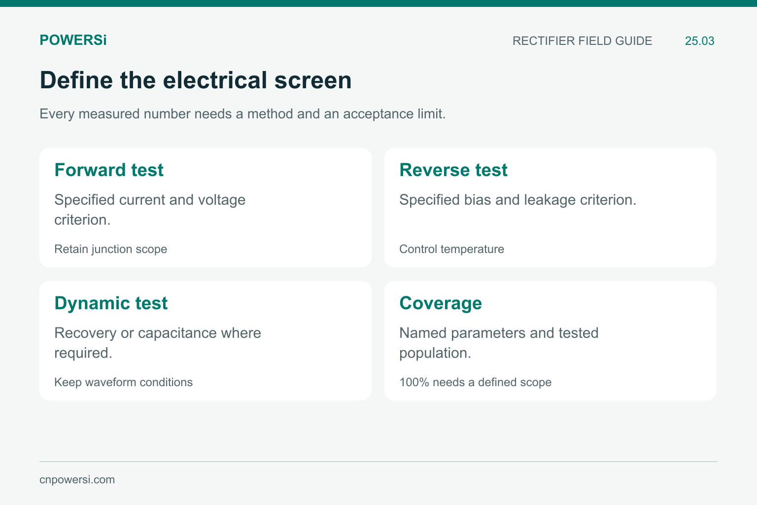
Every measured number needs a method and an acceptance limit.
Stage 3: Finished-Device Electrical Tests
Final electrical checks can include forward voltage at specified current, leakage at specified reverse bias and other parameters required by the device specification. State whether the result applies per junction or per package, especially for dual rectifiers and bridges.
Temperature control, pulse duration, fixture contact and instrument calibration affect the meaning of a measurement. A cold test does not establish a hot leakage limit, and a continuity beep is not a substitute for a power-device electrical acceptance test. Keep the method and limit revision with the result.
Dynamic measurements such as recovery time, recovered charge or capacitance need their own conditions. A statement of “100% electrically tested” does not identify which parameters were screened. Ask for the parameter list and coverage rather than assuming that every dynamic characteristic was measured on every unit.
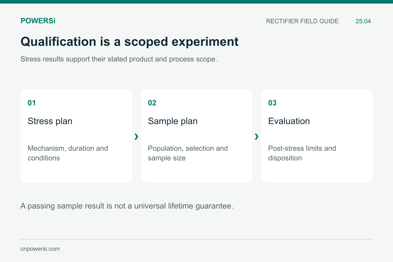
A passing sample result is not a universal lifetime guarantee.
Stage 4: Reliability and Qualification Samples
Reliability evaluation uses selected stresses to investigate mechanisms that may not appear in an initial electrical screen. Depending on the device and qualification plan, examples include temperature cycling, high-temperature reverse bias or humidity-related stresses. The stress, duration, sample size and post-stress criteria define what the result supports.
Semiconductor manufacturers distinguish product and process qualification from routine controls; Nexperia’s quality and reliability overview provides an industry example. A supplier’s particular qualification claim still needs evidence tied to the exact product family and process scope.
Do not turn a successful sample result into a guaranteed service life without an applicable reliability model and mission profile. Likewise, a non-repetitive surge rating is not a direction to apply that surge to every shipped unit. Qualification, characterization and shipment screening have different purposes.
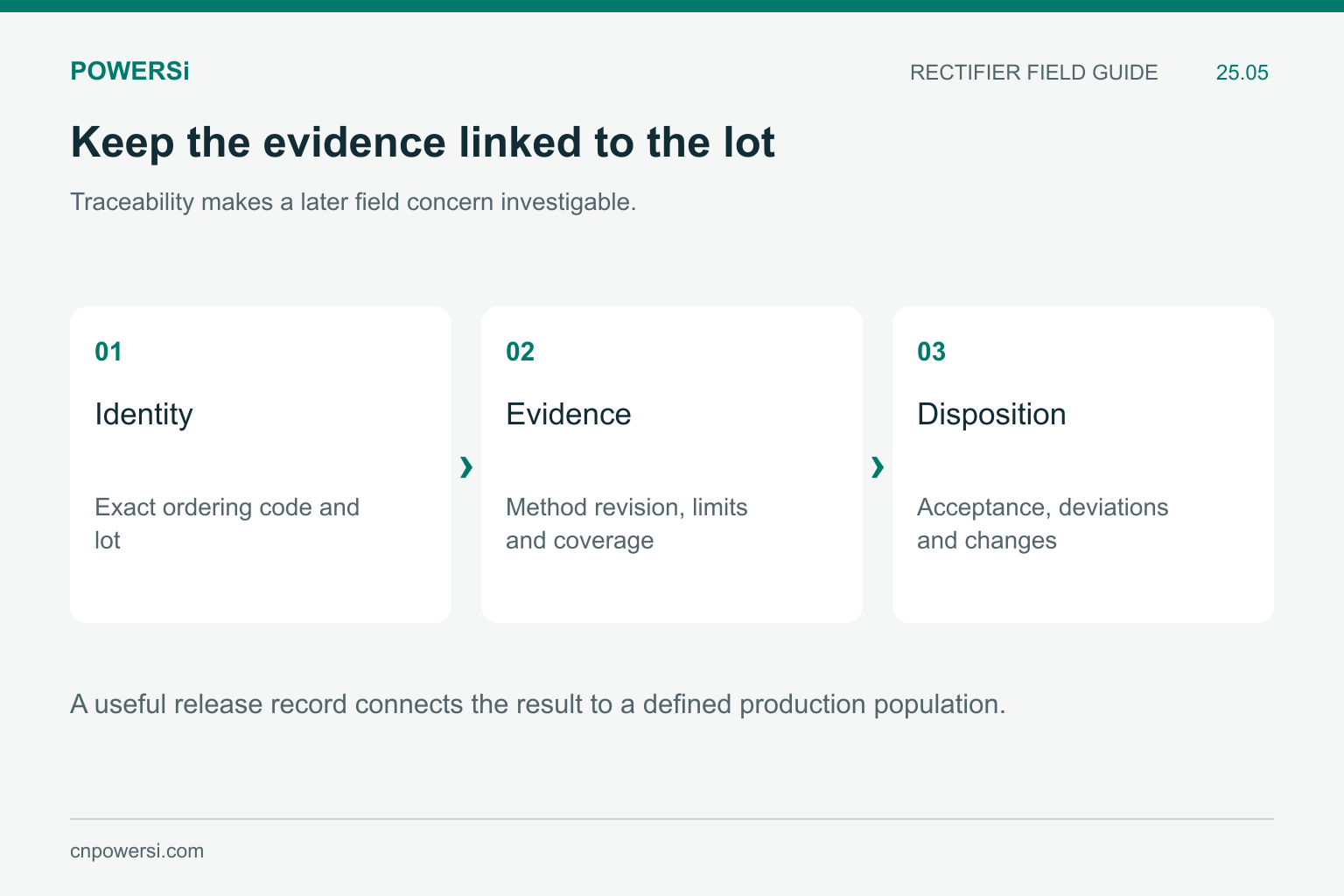
A useful release record connects the result to a defined production population.
Stage 5: Lot Release and Traceability
A useful release record connects the full ordering code, lot identification, applicable specification and test disposition. Where required, it should also identify the sampling plan, deviations and approved process changes. Traceability lets a later field concern be investigated against a defined production population.
| Buyer question | Evidence to request |
|---|---|
| What did every shipped unit receive? | Named screening parameters, limits and conditions |
| What was sampled? | Sample size, selection rule and acceptance criteria |
| What supports reliability? | Relevant qualification scope and stress results |
| Can a field return be traced? | Lot identification and retained record linkage |
The goal is a clear evidence chain, not the longest possible list of test names. A relevant, controlled test with known coverage is more useful than an impressive acronym without conditions.
Key Takeaways
- Separate wafer screening, assembly control, final tests and qualification.
- “100% tested” needs a named parameter list.
- Sampling and destructive tests have defined coverage limits.
- Keep lot identity connected to test methods and disposition.
Conclusion
Good purchasing questions connect a failure concern to a suitable test and a defined population. For POWERSi rectifier requirements, specify the application, acceptance criteria and traceability documents needed for the exact ordering code.
FAQs
Does wafer probing prove that the finished package is reliable?
No. Assembly introduces interfaces and process conditions that require additional controls.
Does 100% testing mean every possible parameter was measured?
No. It describes coverage only for the named screening operations.
Are destructive tests performed on every shipped device?
No. Destructive testing consumes samples and must be distinguished from shipment screening.
Does one qualification result guarantee lifetime in any application?
No. Its relevance depends on the stress scope, product family and intended mission profile.
What should a buyer retain with the test result?
Keep the exact product and lot identity, method revision, conditions, limits, coverage and acceptance decision.


