Skip to content


Product Overview
DSEK1602F combines two 8A fast-recovery paths around a common cathode in ITO-220AB. With a 16A total current rating and 200V reverse blocking, it is suited to positive center-tapped rectification and enclosed power modules.
The 16A total device rating comprises two 8A diode paths. Evaluate each branch at its own current waveform and operating temperature when calculating conduction loss and the required cooling.
Key Features
● 200V repetitive peak reverse voltage and two 8A diode paths.
● 35ns maximum reverse-recovery time under the specified 0.5A test condition.
● 1.05V maximum forward voltage at 8A and 25°C.
● 125A non-repetitive surge current for a 8.3ms pulse.
Key Specifications
| Parameter | Value and conditions |
| Configuration / package | Dual common cathode / ITO-220AB |
| Forward current | 16A per device; 8A per diode |
| Repetitive peak reverse voltage | 200V |
| Forward voltage | 0.75V typ at IF = 4A, Tj = 125°C 1.05V max at IF = 8A, Tj = 25°C |
| Reverse recovery time | 35ns max; Tj = 25°C, IF = 0.5A, IR = 1.0A, Irr = 0.25A |
| Surge current | 125A; non-repetitive, t = 8.3ms |
| Junction to case thermal resistance | 4.5°C/W |
| Junction temperature range | −55°C to +150°C |
Current and thermal limits must be evaluated for the complete assembly. IFSM is a non-repetitive pulse rating, not a repetitive operating-current rating.
Electrical Configuration and Pinout
Two separate anodes connect to a shared cathode. With the marking face toward you and the leads pointing down, the lead functions are A1, K and A2 from left to right. The ITO-220AB package has an insulated outer mounting surface.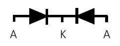
Figure 1. Circuit and connection detail from the DSEK1602F datasheet, page 1. A = anode; K = cathode.
| Connection | Function |
| Left lead | A1 — first diode anode |
| Center lead | K — common cathode |
| Right lead | A2 — second diode anode |
| Mounting surface | Insulated package surface; verify assembly insulation requirements |
Typical Applications
● Positive center-tapped rectification.
● Enclosed SMPS output stages.
● Industrial control power modules.
Common Cathode Rectification in an Insulated Package
The two anodes accept separate winding currents while the shared cathode forms the positive output node. The insulated ITO-220AB body provides a different mounting arrangement from a package with an exposed electrically active tab.
Design Notes
Evaluate each diode at its own current waveform and duty cycle. The 16A total device rating does not mean one junction can carry 16A. Check reverse-voltage peaks, including switching transients, against the 200V rating.
The insulated package surface does not by itself establish complete equipment isolation. Evaluate the thermal interface, creepage, clearance and dielectric requirements of the finished assembly.
The 35ns recovery limit uses the low-current test condition in the parameter table. Evaluate recovery at the application current and temperature. The 125A surge specification is non-repetitive and must not be used as a repetitive overload rating.