Skip to content


Product Overview
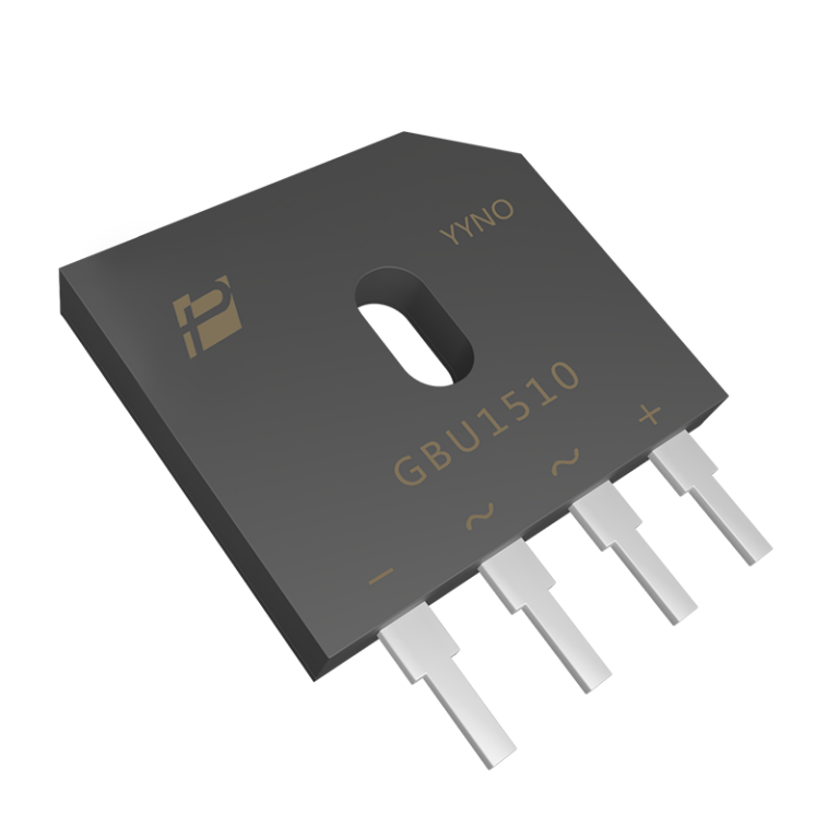
GBU2510 is a 25A 1000V single-phase bridge rectifier in a slim four-terminal GBU package. It supports compact AC-DC input stages that require a defined cooling path and higher current capability.
The 25A operating point requires a heatsink and Tc = 110°C. Two diode junctions conduct in each rectified current path, so bridge-loss calculations must include both forward drops.
Key Features
● 1000V repetitive peak reverse voltage with a 25A current rating.
● GBU four-terminal package with integrated full-wave rectification.
● 1.1V maximum forward voltage at 12.5A and 25°C.
● 300A non-repetitive surge current for a 8.3ms pulse.
Key Specifications
| Parameter | Value and conditions |
| Configuration / package | Single-phase full-wave bridge / GBU |
| Forward current | 25A at Tc = 110°C; with heatsink |
| Repetitive peak reverse voltage | 1000V |
| Forward voltage | 0.87V typ at IF = 12.5A, Tj = 125°C 1.1V max at IF = 12.5A, Tj = 25°C |
| Terminal to case dielectric strength | 2500VAC; 1 minute |
| Surge current | 300A; non-repetitive, t = 8.3ms |
| Junction to case thermal resistance | 1.0°C/W |
| Junction temperature range | −55°C to +150°C |
Current capability depends on case temperature and cooling. Use the datasheet derating curve when determining operating current.
Electrical Configuration and Pinout
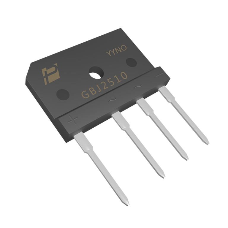
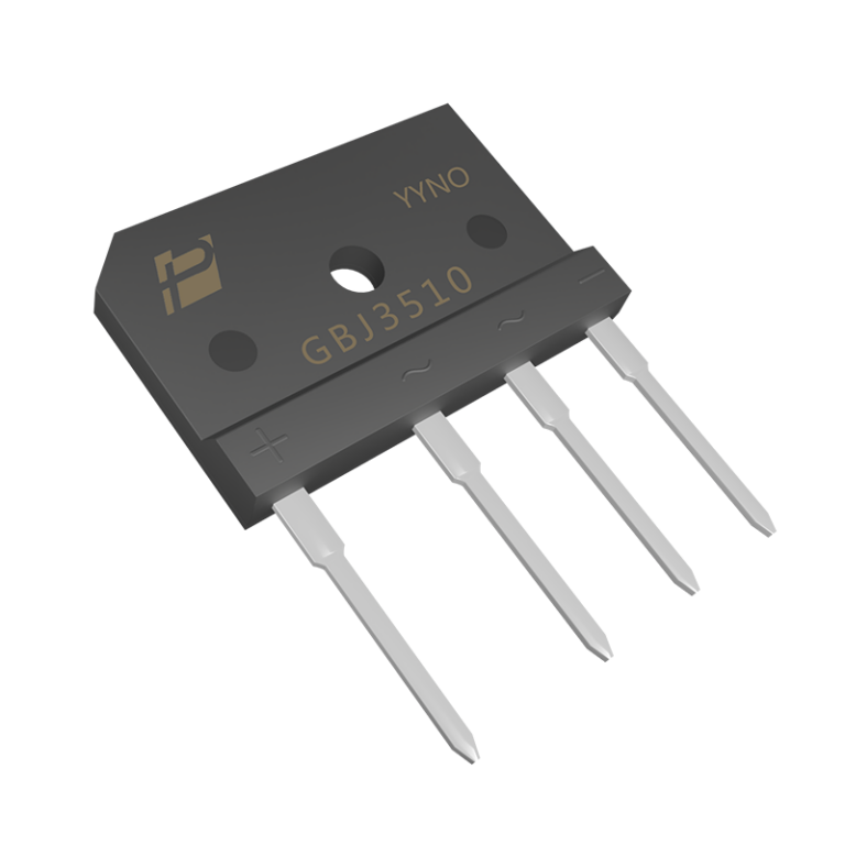
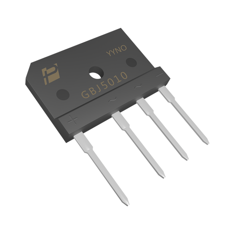
The two terminals marked ~ accept the AC input. The + and − terminals provide the rectified DC output. Follow the polarity markings and the package drawing when laying out the PCB; GBJ and GBU lead arrangements differ.
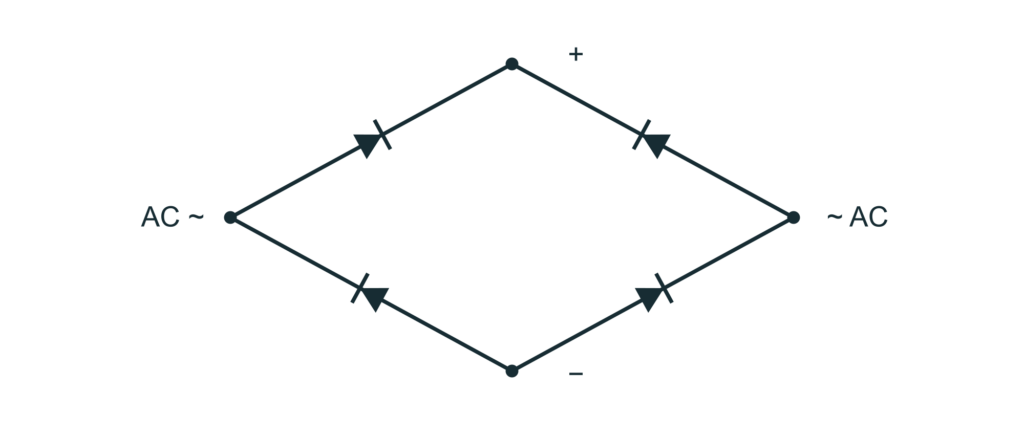
Figure 1. Single-phase full-wave bridge circuit. The terminal symbols correspond to the package markings.
| Connection | Function |
| Terminal marked + | Positive rectified DC output |
| First terminal marked ~ | AC input |
| Second terminal marked ~ | AC input |
| Terminal marked − | Negative rectified DC output |
Typical Applications
● Compact higher-output AC-DC supplies.
● Charger power boards.
● Space-constrained industrial DC-link inputs.
25A Rectification within the GBU Footprint
The 25A grade retains the GBU body format for space-constrained power boards. Increasing bridge current still requires adequate copper, solder joints, surge control and cooling; package size alone does not establish system capability.
Design Notes
The 25A rating requires a heatsink at Tc = 110°C. Include both conducting junctions, the input-current waveform and capacitor-charging pulses in the loss and thermal calculations.
The 2500VAC value is a one-minute terminal-to-case dielectric test. It does not provide galvanic isolation between AC input and DC output. Follow the mounting drawing and include the external thermal interface in the cooling calculation.
The 300A IFSM specification applies to a non-repetitive 8.3ms event. Review inrush limiting, restart conditions, terminal temperature and conductor capacity for the complete input stage.