Skip to content

Product Overview
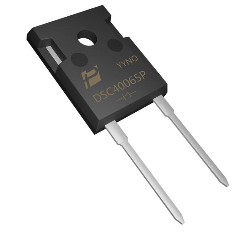
DSC30120P is a 30A 1200V SiC Schottky diode in TO-247AC for high-voltage boost, UPS and DC-DC conversion stages. It combines a defined hot-case current rating with capacitive-charge data at 800V.
The 30A rating is specified at Tc = 140°C. Typical capacitive charge is 155nC at 800V and 25°C, providing a defined point for evaluating commutation behavior.
Key Features
● 1200V repetitive peak reverse voltage with a 30A current rating.
● 155nC typical capacitive charge at 800V and 25°C.
● 1.59V maximum forward voltage at 30A and 25°C.
● 260A non-repetitive surge current for a 8.3ms pulse.
Key Specifications
| Parameter | Value and conditions |
| Configuration / package | Single diode / TO-247AC |
| Forward current | 30A at Tc = 140°C |
| Repetitive peak reverse voltage | 1200V |
| Forward voltage | 1.45V typ / 1.59V max at IF = 30A, Tj = 25°C 2.11V typ / 2.51V max at IF = 30A, Tj = 175°C |
| Capacitive charge | 155nC typ at VR = 800V, Tj = 25°C |
| Surge current | 260A; non-repetitive, t = 8.3ms |
| Junction to case thermal resistance | 0.36°C/W |
| Junction temperature range | −55°C to +175°C |
Current capability depends on case temperature and cooling. Use the datasheet derating curve when determining operating current.
Electrical Configuration and Pinout
With the marking face toward you and the leads pointing down, the left lead is K (cathode) and the right lead is A (anode). The exposed mounting tab is electrically connected to K.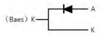
Figure 1. Circuit and connection detail from the DSC30120P datasheet, page 1. A = anode; K = cathode.
| Connection | Function |
| Left lead | K — cathode |
| Right lead | A — anode |
| Metal tab | K — electrically connected to the cathode |
Typical Applications
● High-voltage boost rectification.
● Modular UPS converters.
● Solar string DC-DC conversion stages.
30A SiC Rectification for 1200V Stages
For a 1200V converter that needs the 30A current class, DSC30120P offers 155nC typical capacitive charge at 800V. Compare this charge point together with forward loss and cooling requirements when selecting the rectifier.
Design Notes
The 30A operating point is tied to Tc = 140°C. Include conduction loss, commutation loss, the thermal interface and heatsink when determining usable current. Check reverse-voltage peaks against the 1200V limit.
The metal tab carries the cathode potential. If the heatsink must remain at a different potential, use an appropriate insulating mounting interface and include its thermal resistance.
Capacitive charge is a typical characterization value, not a guaranteed maximum. Compare devices at the same reverse voltage and temperature; converter efficiency also depends on forward loss, the companion switch and operating frequency.