Skip to content


Product Overview
MBR60200PT is a 60A 200V common-cathode dual Schottky rectifier in TO-247AD. Two 30A diode paths serve converter outputs where measured reverse peaks require a higher voltage class.
The 60A total device rating comprises two 30A diode paths. Evaluate each branch at its own current waveform and operating temperature when calculating conduction loss and the required cooling.
Key Features
● 200V repetitive peak reverse voltage and two 30A diode paths.
● Common-cathode TO-247AD package for two rectifier branches.
● 0.95V maximum forward voltage at 30A and 25°C.
● 300A non-repetitive surge current per diode for a 8.3ms pulse.
Key Specifications
| Parameter | Value and conditions |
| Configuration / package | Dual common cathode / TO-247AD |
| Forward current | 60A per device; 30A per diode |
| Repetitive peak reverse voltage | 200V |
| Forward voltage | 0.76V typ at IF = 30A, Tj = 125°C 0.95V max at IF = 30A, Tj = 25°C |
| Reverse leakage at high temperature | 30mA max at VR = 200V, Tj = 125°C |
| Surge current | 300A per diode; non-repetitive, t = 8.3ms |
| Junction to case thermal resistance | 1.0°C/W |
| Junction temperature range | −55°C to +175°C |
Current capability depends on case temperature and cooling. Use the datasheet derating curve when determining operating current.
Electrical Configuration and Pinout
Two separate anodes connect to a shared cathode. With the marking face toward you and the leads pointing down, the lead functions are A1, K and A2 from left to right. The exposed metal tab is also connected to K.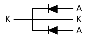
Figure 1. Circuit and connection detail from the MBR60200PT datasheet, page 1. A = anode; K = cathode.
| Connection | Function |
| Left lead | A1 — first diode anode |
| Center lead | K — common cathode |
| Right lead | A2 — second diode anode |
| Metal tab | K — electrically connected to the common cathode |
Typical Applications
● Higher-voltage converter secondary rectifiers.
● Industrial DC bus supplies.
● Battery-conversion output stages.
200V Reverse Blocking for Schottky Outputs
The 200V grade provides additional reverse-voltage headroom while retaining the 30A per-diode architecture. Include its specified hot reverse leakage in the thermal budget, especially during light-load or reverse-biased operating intervals.
Design Notes
Evaluate each diode at its own current waveform and duty cycle. The 60A total device rating does not mean one junction can carry 60A. Check reverse-voltage peaks, including switching transients, against the 200V rating.
The metal tab carries the common cathode potential. If the heatsink must remain at a different potential, use an appropriate insulating mounting interface and include its thermal resistance.
Reverse leakage can contribute significant heat at elevated temperature. Include the 30mA maximum leakage at 200V and 125°C in the reverse-biased loss assessment. The surge limit is a non-repetitive pulse rating.