
MBR60200PT Current Rating: 60 A per Device, 30 A per Diode
Last Updated: 2026-09-17
Quick Answer
The MBR60200PT current rating is 60 A per device and 30 A per diode in the supplied POWERSi V2.0 datasheet. Its two diode sections share a common cathode. Evaluate each section’s current waveform, reverse voltage and temperature before approving the part; the package headline alone does not establish usable output current.
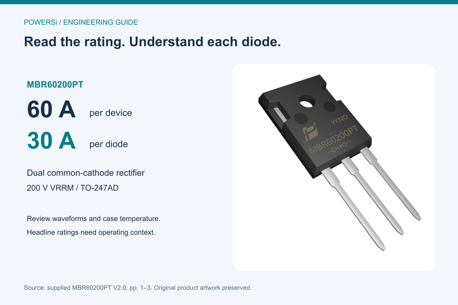
Original supplied product artwork arranged with rating labels; package geometry and markings are preserved.
What the MBR60200PT current rating actually describes
A purchase request that says only “60 A, 200 V Schottky diode” leaves an important question unanswered: how is current distributed inside the package? The supplied MBR60200PT datasheet identifies a dual common-cathode device in a TO-247AD package. Page 2 lists average forward current separately as 60 A per device and 30 A per diode. These are different rating scopes, not interchangeable descriptions of a single diode path.
For a design using only one section, the 60 A device headline cannot be assigned to that section. In an alternating rectifier arrangement, calculate the average and peak currents in each section over the full switching period. A balanced waveform can distribute average current across the two sections, but the actual conduction intervals, ripple and heat dissipation still need review. Connecting the two anodes together also requires a current-sharing and thermal assessment; it does not create an unconditional 60 A operating guarantee.
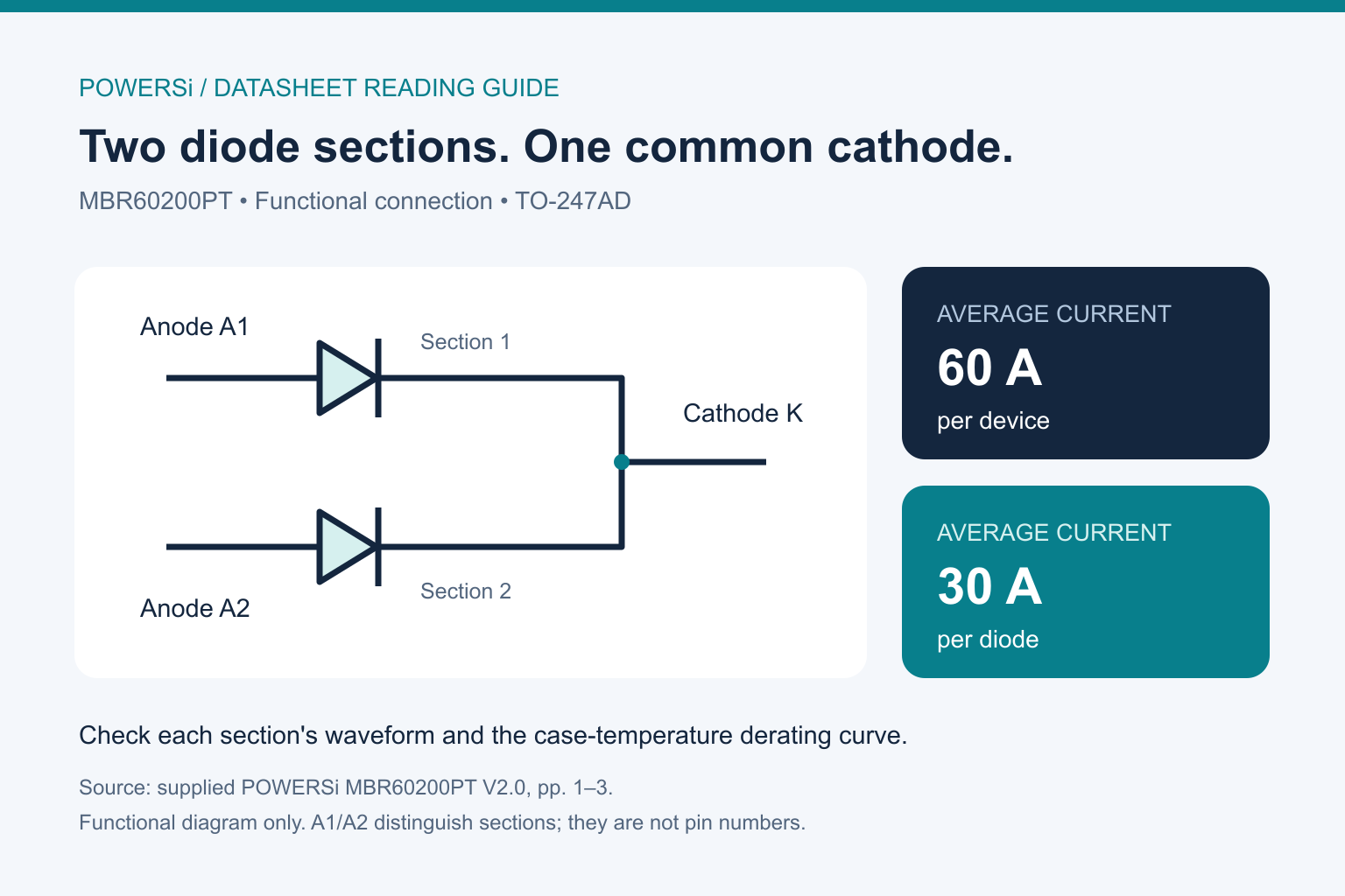
Functional connection adapted from datasheet page 1; current ratings from page 2. This is not a physical pin-number or PCB layout drawing.
Match each number to its test condition
The following values come from the supplied MBR60200PT V2.0, pages 1–3. Confirm the current controlled revision with POWERSi before design release.
| Parameter | Published value | How to use it |
|---|---|---|
| Repetitive peak reverse voltage, VRRM | 200 V | Evaluate the blocking voltage across each diode, including overshoot. |
| Average forward current, IF(AV) | 60 A per device; 30 A per diode | Check both rating scopes and the case-temperature derating curve. |
| Non-repetitive surge current, IFSM | 300 A per diode, single pulse, 8.3 ms | Not a repetitive operating-current rating. |
| Forward voltage, VF | 0.95 V maximum at IF = 30 A, Tj = 25°C | A maximum at this stated test point. |
| Forward voltage, VF | 0.76 V typical at IF = 30 A, Tj = 125°C | A typical hot-junction value, not a guaranteed maximum. |
| Reverse leakage, IR | 0.03 mA maximum at Tj = 25°C, VR = VRRM | Preserve both temperature and reverse-voltage conditions. |
| Reverse leakage, IR | 30 mA maximum at Tj = 125°C, VR = VRRM | Use the maximum column when checking this specified limit. |
| Maximum junction temperature | 175°C | An upper rating, not a recommended operating target. |
The current-rating row does not state a case-temperature condition beside the 60 A figure. Page 3 provides an IF–Tc curve that falls as case temperature rises. Review that curve and obtain clarification of the applicable waveform and thermal conditions instead of assigning the headline rating to an arbitrary ambient temperature.
Why the leakage-current columns matter
Page 1 quotes 1.0 mA typical at 200 V and 125°C. Page 2 quotes 30 mA maximum at VR = VRRM and Tj = 125°C. They describe different statistical categories; substituting one for the other can substantially change a preliminary loss estimate.
For illustration, a reverse-biased section at 200 V and 30 mA dissipates 6 W at that operating point, from P = V × I. Using 1 mA gives 0.2 W. These are simple operating-point calculations, not predictions of average converter loss. Actual reverse-voltage waveforms, blocking duration and junction temperature determine the average contribution. In particular, the 125°C limit should not be extrapolated into a guaranteed value at 175°C.
Similarly, multiplying 30 A by the typical 0.76 V gives 22.8 W for continuous conduction at that specified point. A switched waveform requires averaging instantaneous forward loss over time. Neither this calculation nor the reverse-loss example establishes a permissible system operating point on its own.
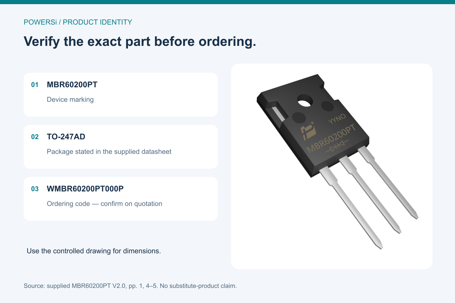
Use the controlled package drawing to approve dimensions and lead assignments; a photograph is an identification aid.
Keep connection and mounting reviews together
The datasheet drawing shows two anodes and a shared cathode; it also marks the tab as K. Check the physical lead order against the drawing and the board orientation before assembly. When the heatsink must be at a different electrical potential, engineering needs to review the insulation arrangement as part of the thermal design.
Page 2 lists junction-to-case thermal resistance as 1.0°C/W. Do not treat this as junction-to-ambient resistance. The interface, heatsink and airflow add to the heat path. The table does not explicitly resolve every detail of the dual-section thermal model, so request clarification before assigning the listed value to a simultaneous two-section loss calculation.
The package has a mounting hole, but hole presence alone does not establish a screw torque, insulator specification or assembly procedure. Obtain the applicable mounting guidance, verify the interface materials and measure case temperature in the intended enclosure. Mechanical strain on the leads and solder joints also belongs in the assembly review.
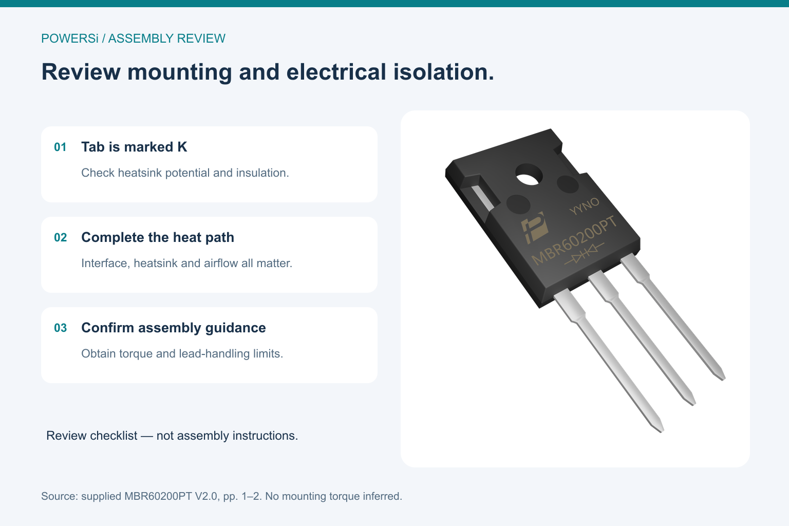
Mounting review checklist with the original product artwork. It does not specify torque, insulation hardware or an approved assembly.
Define a useful sample-validation request
Before ordering samples, give the supplier a short operating brief. Include the circuit topology, current through each diode section, switching frequency, expected reverse voltage and overshoot, case-temperature target and cooling arrangement. Describe startup and fault pulses separately from normal operation. The 300 A figure is a non-repetitive 8.3 ms surge rating, so a train of startup pulses needs its own evaluation.
For procurement, request the exact ordering code and package drawing, a controlled datasheet revision and the agreed sample acceptance checks. The supplied V2.0 ordering table lists WMBR60200PT000P with MBR60200PT marking in TO-247AD. Confirm the ordering details on the quotation; do not infer interchangeability from a similar model name or package silhouette.
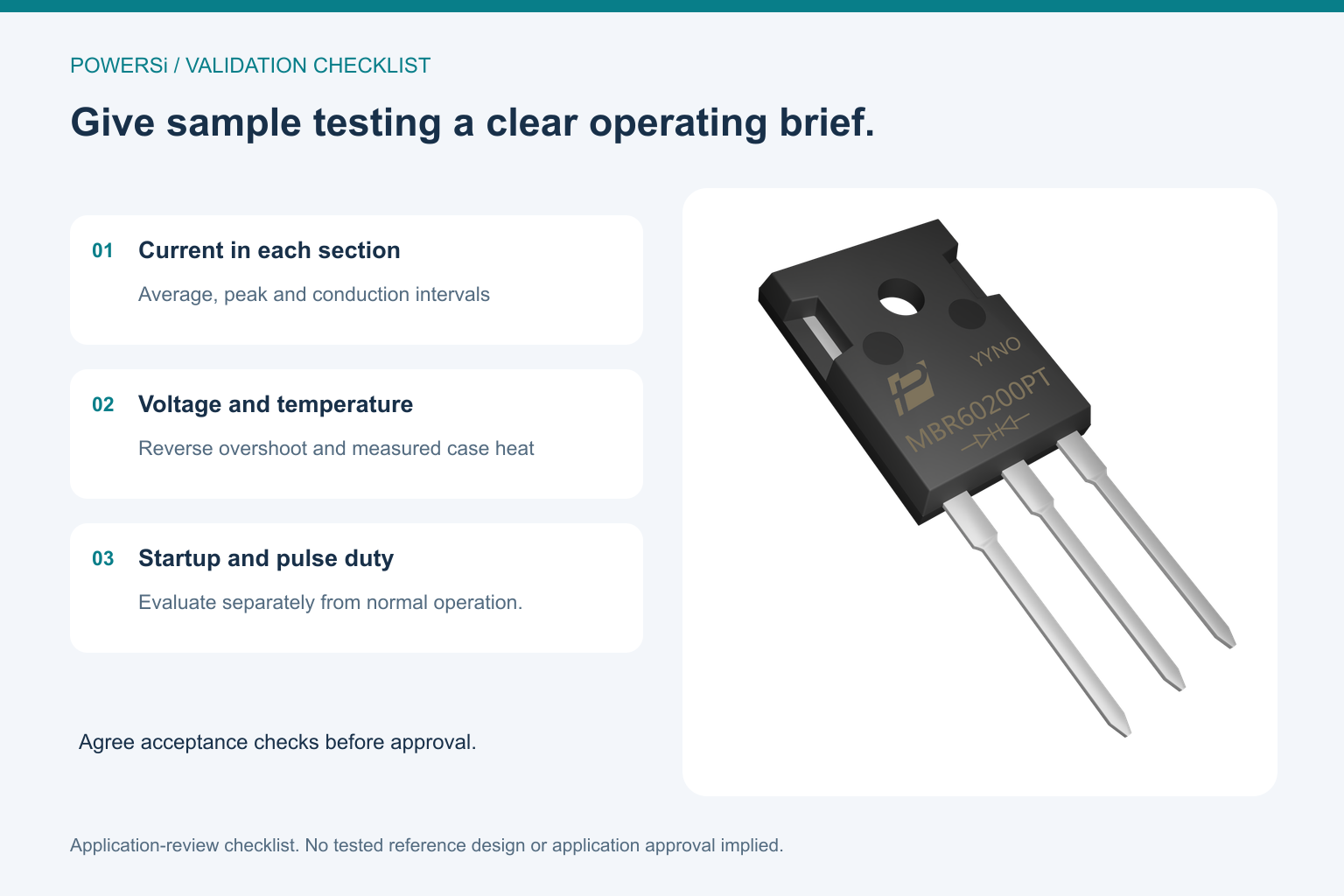
Sample-validation checklist, not a tested POWERSi reference design or evidence of application approval.
Key Takeaways
- Track average current per diode section as well as the device-level rating.
- Keep typical and maximum VF and IR values separate, with their test conditions.
- Review reverse-voltage overshoot and case-temperature derating in the actual circuit.
- Verify common-cathode connections, tab potential and the controlled package drawing.
- Specify surge duty and sample acceptance conditions before procurement approval.
Conclusion
The useful starting point for MBR60200PT evaluation is the division between its two diode sections. A design review should connect each section’s current and blocking waveform to its electrical limits and thermal conditions. A procurement review should then preserve the exact part identity and agreed verification requirements.
Explore the POWERSi product catalog and send your operating brief to [email protected] to request the current MBR60200PT datasheet, package drawing and sample-evaluation support.
FAQs
Does 60 A mean either diode can continuously carry 60 A?
No. The supplied datasheet lists 60 A per device and 30 A per diode. Each section must be evaluated within its applicable electrical and thermal conditions.
Is MBR60200PT a bridge rectifier?
No. Its datasheet shows two diode sections connected to a common cathode. It is not a four-diode full bridge.
Is 0.76 V a guaranteed maximum forward voltage?
No. It is a typical value at IF = 30 A and Tj = 125°C. The supplied table separately gives 0.95 V maximum at IF = 30 A and Tj = 25°C.
Which 125°C leakage value should a limits review use?
Distinguish the 1.0 mA typical summary value from the 30 mA maximum table value, both at the stated 200 V reverse-voltage condition. Use the maximum specification for that limits check and evaluate the actual blocking waveform for average loss.
Can the heatsink be assumed electrically isolated?
No. The supplied package drawing marks the tab as K. Verify the electrical potential, physical construction and any required insulation against the controlled drawing and mounting guidance.
What should be included in a sample inquiry?
Include the exact model, topology, per-section current waveform, reverse voltage with overshoot, switching frequency, cooling arrangement, temperature target and startup conditions. Ask for the current datasheet revision and agree the acceptance checks.

