Skip to content

1. Application Scenarios
Electric vehicle charging stations are divided into AC slow charging (7kW-22kW) and DC fast charging (30kW-350kW), used to charge electric vehicle power batteries.
2. System Architecture/Application Topology Diagram
Typical topology (DC fast charging): AC input → PFC (Vienna/three-level) → DC/DC isolated conversion (LLC/PSFB) → DC output
3. The Role of the Product in the System
| Product Category | System Function |
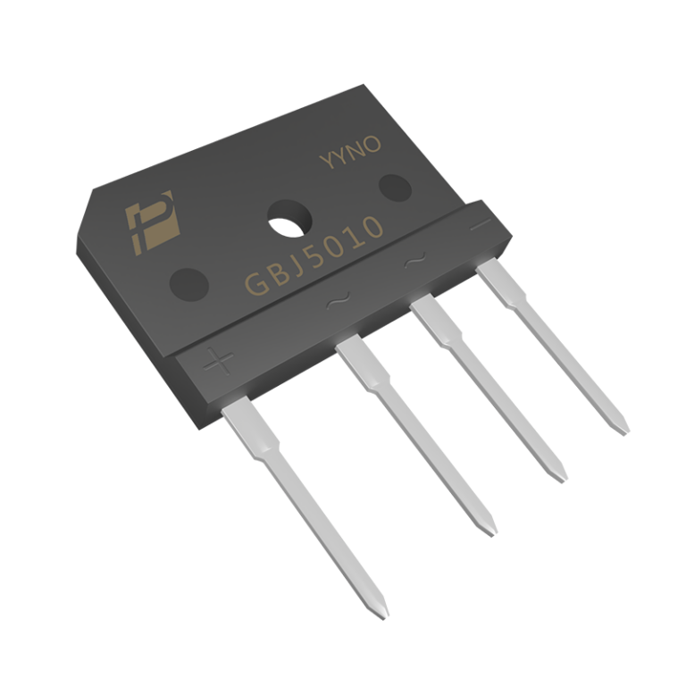
| Rectifier bridge | Front end three-phase rectification, converting AC to DC bus |
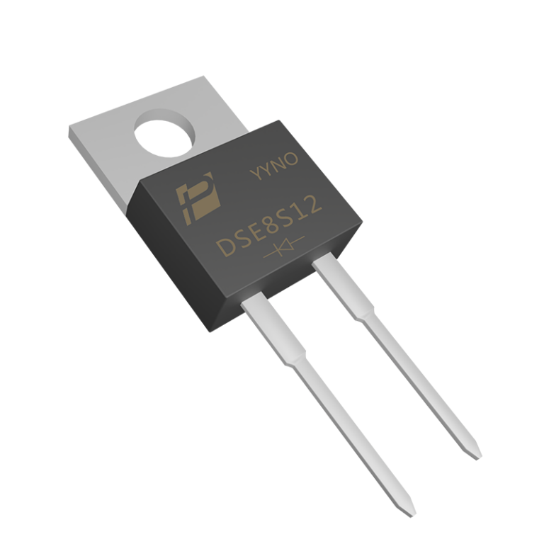
| SiC diode | PFC boost diode (Vienna PFC), zero reverse recovery |
| Fast recovery diode | DC/DC level output rectification (LLC synchronous rectification or diode rectification) |
4. Recommended Rroduct Model
| Product Category | Recommended Series/Model | Key Parameters |
| three-phase rectifier bridge | GBJ/KBJ series (50A – 100A/1600V) | Strong surge resistance capability |
| SiC diode | 650V/1200V(10A–60A) | Vienna PFC Ideal Choice |
| Ultra soft recovery diode | USR series (600V/1200V) | DC/DC rectifier stage |
5. AC/DC Module Application
● The DC fast charging front-end is a three-phase Vienna PFC, which converts AC to an 800V DC bus
● Using SiC diode+IGBT/SiC MOSFET combination
6. Application of PFC Circuit
● Vienna PFC is the mainstream PFC topology for charging stations
● Recommended solution: 6 SiC SBDs+3 IGBT/SiC MOSFETs
● Advantages: THD<5%, PF>0.99, efficiency>98%
7. Common Customer Needs
| Demand | Our Response |
| The charging module must pass CCS/CHAdeMO certification | Provide AEC-Q101 certification documents for the device |
| To be compatible with the global power grid (AC 200-480V) | Recommend wide voltage input devices with sufficient voltage margin |
| The volume of the fast charging module should be small | Recommend high-frequency SiC solution to reduce transformer and filter inductance |
| Limited heat dissipation conditions | Recommend low VF SiC diodes to reduce conduction losses |