Skip to content

1. Application Scenarios
Photovoltaic inverters convert the direct current generated by solar panels into alternating current for grid connected or off grid use, covering series (3-100kW), centralized (>100kW), and micro inverters (<3kW).
2. System Architecture/Application Topology Diagram
Typical topology: PV input → DC/DC boost → DC/AC inverter (full bridge/LLC) → grid connected
3. The Role of the Product in the System
| Product Category | System Function |
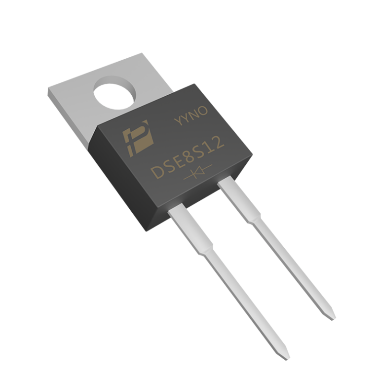
| SiC diode | Boost stage is used as a boost diode, with zero reverse recovery, greatly improving efficiency |
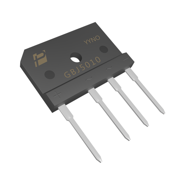
| Rectifier bridge | Used for auxiliary power supply AC/DC rectification |
| Fast recovery diode | LLC resonant cavity rectification output, or flyback auxiliary power supply RCD absorption |
4. Recommended Product Model
| Product Category | Recommended Series/Model | Key Parameters |
| SiC diode | 650V/1200V SiC diode (5A-40A) | Qc low, VF stable |
| Rectifier bridge (auxiliary power supply) | MBS patch bridge or GBU series | 600V/1A–8A |
| Fast recovery diode | DES series (600V) | Trr < 60ns |
5. AC/DC Module Application
● The internal auxiliary power supply of the inverter adopts flyback AC/DC, using MOSFET+RCD diode (FRD)
● Grid side isolation adopts power frequency transformer or high-frequency isolation scheme
6. Application of PFC Circuit
● Adopting Boost PFC topology, SiC diode+MOSFET combination
● Advantages: High frequency (>100kHz), small inductance volume, efficiency>99%
7. Common Customer Needs
| Demand | Our Response |
| European customers require conversion efficiency>98.5% | Provide SiC solutions and third-party efficiency testing reports |
| The product must meet VDE-AR-E 4010 certification | Provide device compliance documents |
| Inverter operates in high temperature environment (60 ° C) | Provide high-temperature reliability test data (175 ° C junction temperature) |
| Need for lightweight design | Recommend high-frequency SiC solution to reduce magnetic components |